26 PowerFlex® 700S Drives - Phase I Control (Frame Sizes 9 & 10)
DC Input Precharge Control Wiring
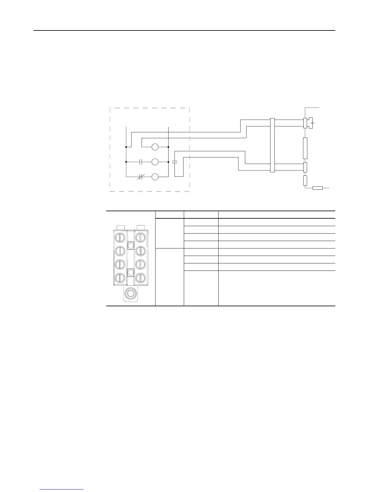
If you are installing a DC input drive with a precharge interlock you must make the
following connections on the X50 terminal block from the precharge circuit.
Important: Precharge circuitry is external to the drive.
Figure 2 Sample Precharge Wiring Diagram (Frame 9 Shown)
Table D X50 Terminal Block Connections
Frame X50 Terminal Description
9 1 Charge Relay Contact
2 Charge Relay Contact
3 Precharge Complete Signal (+24V DC)
4 Precharge Complete Signal (Common)
10 21 Charge Relay Contact
23 Charge Relay Contact
25 Precharge Complete Signal (+24V DC)
26 Precharge Complete Signal (Common)
X10
X7
X9
X6
X1
X50
CR1
Pilot Relay
CR1
M
Main DC Contactor
M
CR2
Precharge
1
2
5
6
M
DC Bus
Precharge
Control

 Loading...


