PowerFlex® 700S Drives - Phase I Control (Frame Sizes 9 & 10) 45
Important: In 2-wire mode, the drive will start when the HIM “Start” is pressed and
stop when the HIM “Start” is released. The recommended mode of use
for the Start-Up Routine is 3-wire control, Parameter 153 [Control
Options], Bit 8 set to “1”.
Step 11: Running Drive
from HIM (Optional)
Follow these instructions to run the drive in a very basic fashion from the HIM. This
step is very useful when commissioning a complex system.
Using the HIM, make the following parameter settings to allow the HIM to control
the drive:
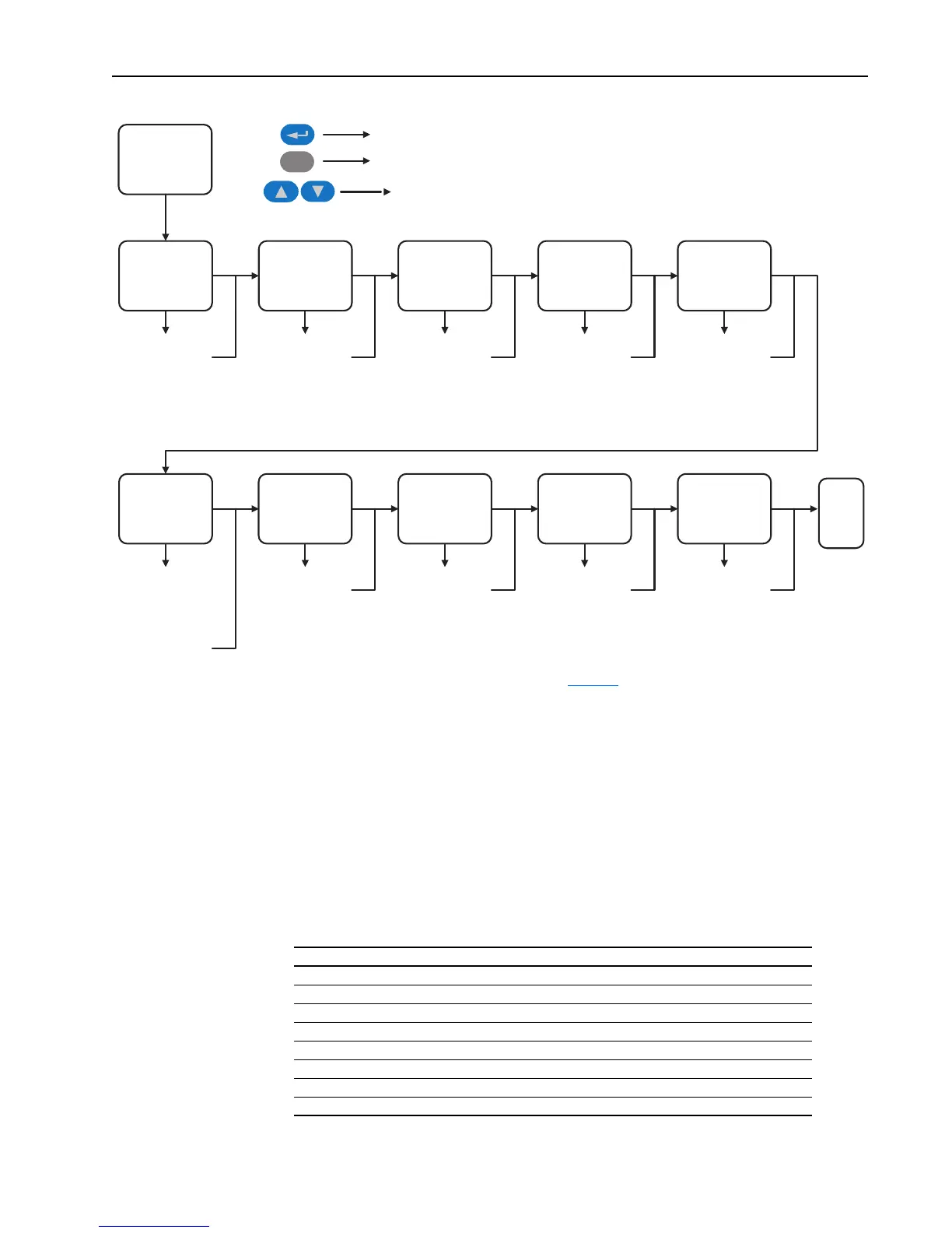
PowerFlex 700S
Start-Up
Motor Control Motor Data
Feedback
Configuration
Power Circuit Test Direction Test
Motor Tests Inertia Measure Speed Limits Speed Control Start / Stop / I/O
Select Motor Control
Mode
Select DB Resistor
Enter Motor NP Data
Power & Units
FLA
Vol ts
Hertz
RPM
Poles
Setup / Select
Encoder
Resolver
Hi-Res Encoder
Linear Sensor
Diagnostic Check for
Drive Power Circuit
Verify Direction
Field Oriented
Control: Measure
Stator Resistance,
Leakage Inductance,
Magnetizing
Inductance
PMag Motor: Encoder
Offset, Stator
Resistance, Stator
Inductance, Back EMF
Measure System
Inertia
Select Direction
Control
Set FWD, REV and
ABS Speed Limits
Select Sources For All
Speed References
Configure:
Digital Inputs, Digital
Outputs, Analog
Inputs, Analog Outputs
Done /
Exit
Esc
Down 1 level or Select
Back 1 level or 1 selection
Scroll all choices
(1)
(1)
See “Important” statement about the HIM on page 44
Set this parameter ... ... to this value
Parameter 16 [Speed Ref Sel] 0100 0000
Parameter 691 [DPI Ref Sel] 1 “Local HIM”
Parameter 693 [Logic Mask] 0000 0000 0000 0010
Parameter 694 [Start Mask] 0000 0000 0000 0010
Parameter 695 [Jog Mask] 0000 0000 0000 0010
Parameter 696 [Direction Mask] 0000 0000 0000 0010
Parameter 697 [Fault Clr Mask] 0000 0000 0000 0010
Parameter 222 [Motor Fdbk Sel] 2 “Sensorless”

 Loading...


