18 PowerFlex® 700S Drives - Phase I Control (Frame Sizes 9 & 10)
Removing the Covers from Frame 10 Size Drives
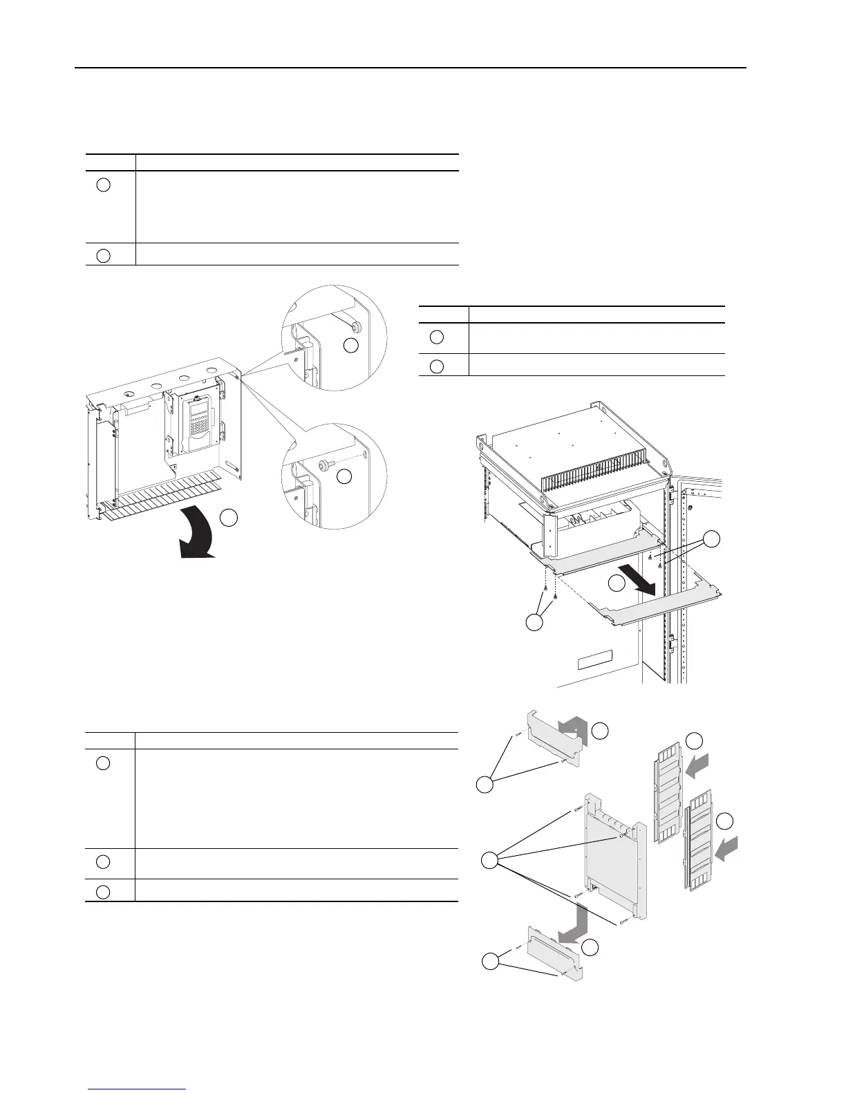
Moving Control Frame
Task Description
Loosen the two T8 Torx-head screws, which secure the Control Frame
to the drive enclosure (Frame 10 drives, from early production runs,
have holes instead of slots for these screws. You must completely
remove the screws from these drives in order to swing-open the control
frame.).
Swing the Control Frame out and away from the power structure.
A
B
Removing the Airflow Plate
Task Description
Remove the four T8 Torx-head screws which secure the
airflow plate to the drive.
Slide airflow plate off of the drive.
C
D
Removing Protective Covers
Task Description
Remove the four M5 POZIDRIV screws which secure the top and
bottom protective covers to the main front protective cover, then
remove the top and bottom protective covers.
Note: You only need to remove the top and bottom covers to gain
access to the power terminals. You can remove the other covers
without removing the top and bottom covers.
Remove the four M5 POZIDRIV screws which secure the main front
protective cover to the drive, then remove the protective cover.
Remove side protective covers.
E
F
G
B
or
A
A
C
D
C
E
E
E
E
F
G
G

 Loading...


