34 PowerFlex® 700S Drives - Phase I Control (Frame Sizes 9 & 10)
I/O Terminal Blocks
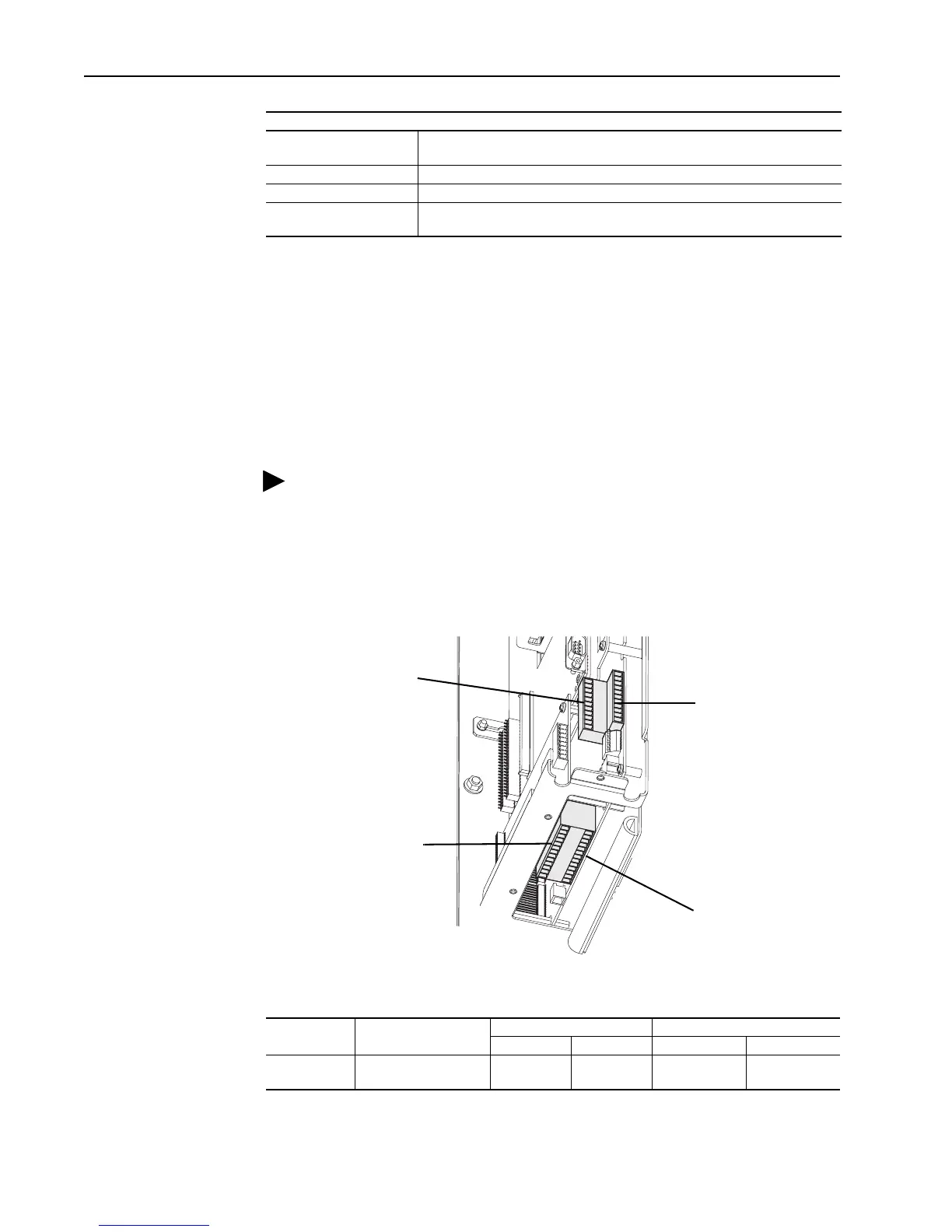
Wiring the Main Control Board I/O Terminals
Terminal blocks TB1 and TB2 contain connection points for all inputs, outputs and
standard encoder connections. Both terminal blocks reside on the Main Control
Board.
Remove the terminal block plug from the socket, and make connections.
Reinstall the plug, when wiring is complete. The terminal blocks have keys, which
make it difficult to insert a terminal plug into the wrong socket.
Figure 7 Main Control Board I/O Terminal Locations
Table I Control & Encoder Terminal Block Specifications
Minimum inside bend radius 25.4mm (1 in.) Any bends with a shorter inside radius can permanently damage
the fiber optic cable. Signal attention increases with decreased inside bend radius.
Operating Wavelength 650 nm (Red)
Data Rate 5 Mbps
Maximum Node Count • 10 - Daisy Chain
• 256 - Star Configuration
Specification
TIP: Remember to route wires through the sliding access panel at the
bottom Control Assembly.
Name Description
Wires Size Range
(1)
(1) Maximum/minimum sizes the terminal block will accept - these are not recommendations.
Torque
Maximum Minimum Maximum Recommended
I/O & Encoder
Blocks
Signal & Encoder power
connections
1.5 mm
2
(16 AWG)
.14 mm
2
(28 AWG)
.25 N-m
(2.2 lb.-in.)
.22 N-m
(1.9 lb.-in.)
TB1
TB2
TB1 - Row T (Top)
TB1 - Row B (Bottom)
TB2 - Row T (Top)
TB2 - Row B (Bottom)

 Loading...


