32 PowerFlex® 700S Drives - Phase I Control (Frame Sizes 9 & 10)
Switches SW2-1, 3, and 5 are for the secondary encoder. Set these switches to match
the encoder output specifications. Open these switches for 12V DC operation, close
them for 5V DC operation.
Encoder Output Settings
Jumper J6 on the main control board configures the encoder power supply for either
5V dc or 12V dc operation. Place the jumper on pins 1 and 2 for 12V operation.
Place it on pins 2 and 3 for 5V dc operation.
Auxiliary Power Supply
You may use an auxiliary power supply to keep the 700S Control Assembly
energized, when input power is de-energized. This allows the Main Control Board,
DriveLogix controller and any feedback option cards to continue operation. Connect
auxiliary power to J15 on the High Power Interface board. You must set parameter
153 [Control Options], bit 17 [Aux Pwr Sply] to enable this feature.
Table F Auxiliary Power Supply Specifications
Connecting SynchLink
SynchLink provides high-speed synchronization and communication between
multiple PowerFlex 700S drives (or other products with SynchLink capability).
Voltage Current (Min) Power (Min)
24V dc ± 5% 3A 75W
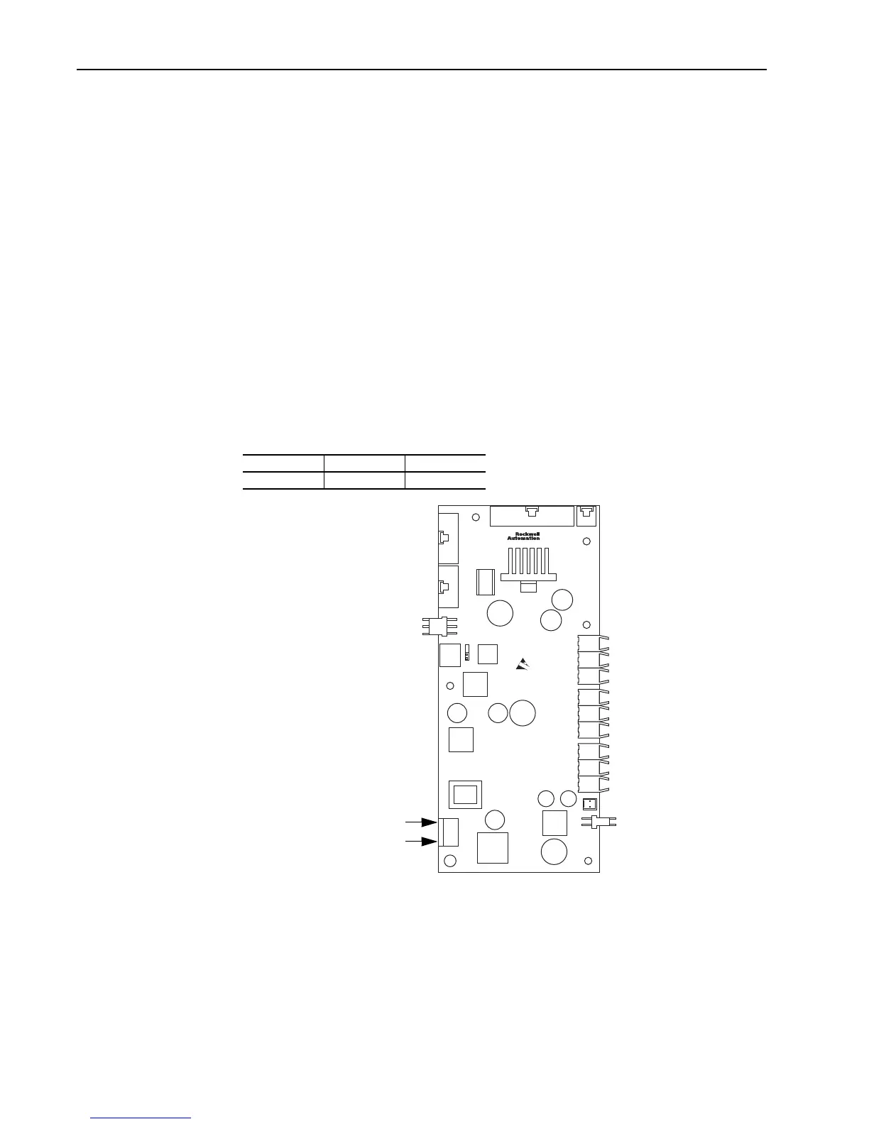
High Power
Interface Board
J15 Auxiliary
Power Connector
Pin 1 (24V dc power)
Pin 3 (24V dc common)

 Loading...


