28 PowerFlex® 700S Drives - Phase I Control (Frame Sizes 9 & 10)
Power Wiring Instructions
• For power wiring instructions for frame 9 size drives, see “Frame 9 Size Drives
Power Terminal Specifications” below.
• For power wiring instructions for frame 10 size drives, see Frame 10 Size Drives
Power Terminal Specifications on page 29.
Frame 9 Size Drives Power Terminal Specifications
No. Name Description
Wire Size Range
(1)
Torque
Maximum Minimum Recommended
➊
Input Power Terminal Block
(2)
L1, L2, L3
Input power 185.0 mm
2
(350 MCM)
95.0 mm
2
(4/0 AWG)
40 N-m
(354 lb.-in.)
➋
Output Power Terminal Block
(2)
U/T1, V/T2, W/T3
Motor connections 185.0 mm
2
(350 MCM)
95.0 mm
2
(4/0 AWG)
40 N-m
(354 lb.-in.)
➌
SHLD Terminal, PE, Motor Ground Terminating point for wiring shields 95.0 mm
2
(4/0 AWG)
5.0 mm2
(10 AWG)
22 N-m
(195 lb.-in.)
➍
DC Bus
(3)
(2 Terminals; DC–, DC+)
DC input or external brake
(Internal Brake option not ordered)
185.0 mm
2
(350 MCM)
95.0 mm
2
(4/0 AWG)
40 N-m
(354 lb.-in.)
DC Bus w/Brake
(3)
(3 Terminals; DC–, DC+/R+, R–)
DC input/internal brake
(Internal Brake option is ordered)
185.0 mm
2
(350 MCM)
95.0 mm
2
(4/0 AWG)
40 N-m
(354 lb.-in.)
➎
Cable Clamp for Shield
(1) Maximum/minimum sizes that the terminal block will accept - these are not recommendations.
(2) Do Not exceed maximum wire size. Parallel connections may be required.
(3) DC terminal and brake lugs can be removed.
D
C
–
D
C+/R
+
R–
➊
➌
➍
➋
➎
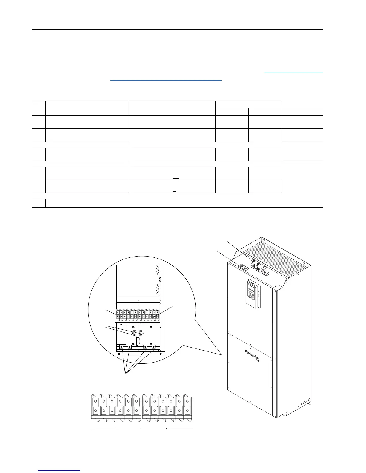
Figure 5 Power Terminal Block
(2)
➌
L1
AC Line Input Power To Motor Leads
L2 L3 L1 L2 L3 U/T1 V/T2 W/T3 U/T1 V/T2 W/T3

 Loading...


