8 PowerFlex® 700S Drives - Phase I Control (Frame Sizes 9 & 10)
Step 3: Lifting the Drive • For lifting instructions for frame 9 size drives, see “Frame 9 Size Drives” below.
• For lifting instructions for frame 10 size drives, see Frame 10 Size Drives
on
page 9.
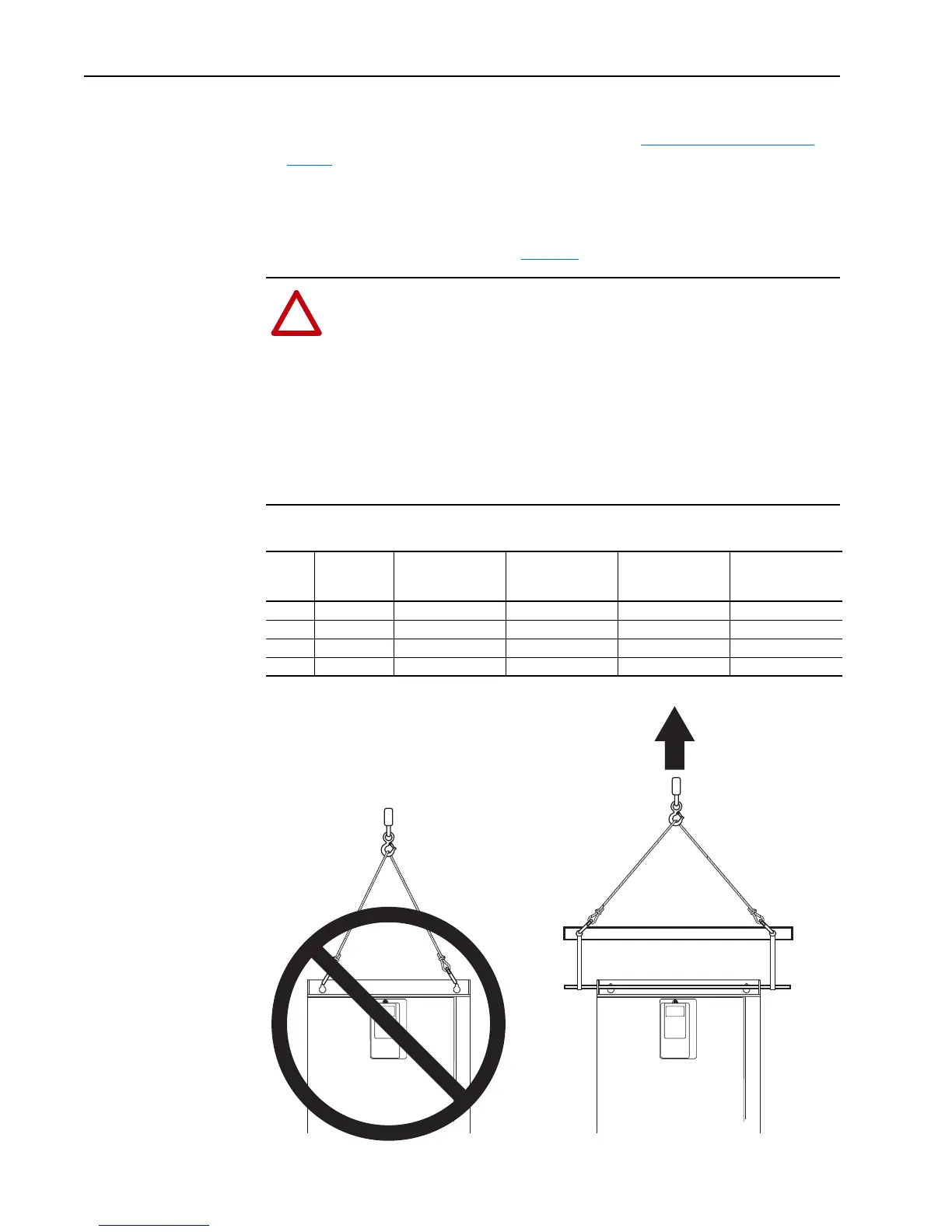
Frame 9 Size Drives
Important: When lifting a frame 9 size drive, a rod must be placed between the
lifting holes as shown in Figure 1
below.
Figure 1 Frame 9 Lifting
!
ATTENTION: To guard against possible personal injury and/or equipment
damage...
• Remove any wiring access covers at the top of the drive.
• Do Not allow any part of the drive or lifting mechanism to make
contact with electrically charged conductors or components.
• At no time should a person or their limbs be directly underneath the
items being lifted.
• Do not subject the load to high rates of acceleration or deceleration.
• Inspect all lifting hardware for proper attachment before lifting drive
unit.
Voltage
Class
Drive Rating
Amps
AC Input Drive &
Enclosure
Weight kg (lbs.)
AC Input Drive &
Packaging
Weight kg (lbs.)
DC Input Drive &
Enclosure
Weight kg (lbs.)
DC Input Drive &
Packaging
Weight kg (lbs.)
400V 261 143 (315) 143 (315) 109 (240) 109 (240)
400V 300 151 (333) 151 (333) 117 (258) 117 (258)
600V 170 143 (315) 143 (315) 109 (240) 109 (240)
600V 208 143 (315) 143 (315) 109 (240) 109 (240)

 Loading...


