Reflected Wave 2-127
Reflected Wave [Compensation]
The pulses from a Pulse Width Modulation (PWM) inverter using IGBTs
are very short in duration (50 nanoseconds to 1 millisecond). These short
pulse times combined with the fast rise times (50 to 400 nanoseconds) of
the IGBT, will result in excessive over-voltage transients at the motor.
Voltages in excess of twice the DC bus voltage,(650V DC nominal @ 480 V
input) result at the motor and can cause motor winding failure.
The patented reflected wave correction software in the PowerFlex 70 will
reduce these over-voltage transients from a VFD to the motor. The
correction software modifies the PWM modulator to prevent PWM pulses
less than a minimum time from being applied to the motor. The minimum
time between PWM pulses is 10 microseconds. The modifications to the
PWM modulator limit the over-voltage transient to 2.25 per unit volts
line-to-line peak at 600 feet of cable.
400 V Line + 10% High Line = 540V DC bus X 2.25 = 1200 V
480 V Line + 10% High Line = 715V DC bus X 2.25 = 1600 V
600 V Line + 10% High Line = 891V DC bus X 2.25 = 2000 V
(inverter duty grade motor insulation)
The software is standard and requires no special parameters or settings.
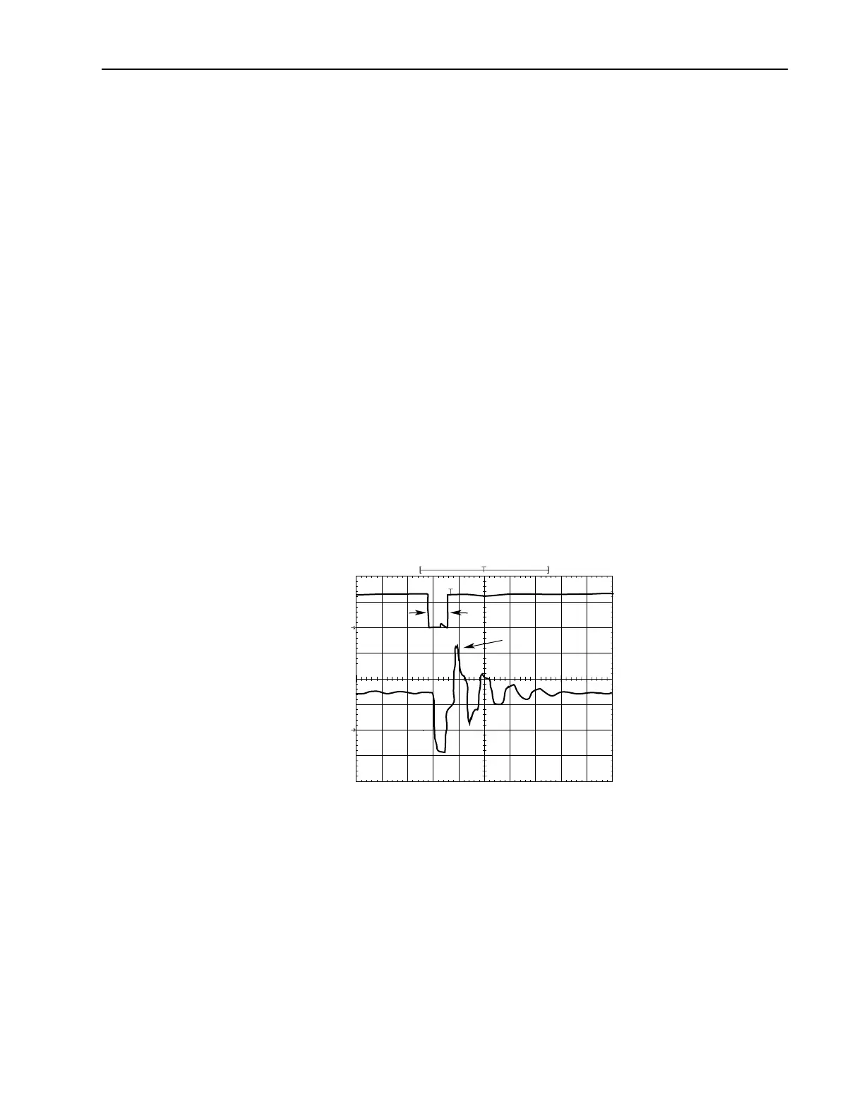
The above figure shows the inverter line-to-line output voltage (top trace)
and the motor line-to-line voltage (bottom trace) for a 10 HP, 460V AC
inverter, and an unloaded 10 HP AC induction motor at 60 Hz operation.
500 ft. of #12 AWG PVC cable connects the drive to the motor.
Initially, the cable is in a fully charged condition. A transient disturbance
occurs by discharging the cable for approximately 4ms. The propagation
delay between the inverter terminals and motor terminals is approximately
1ms. The small time between pulses of 4ms does not provide sufficient time
to allow the decay of the cable transient. Thus, the second pulse arrives at a
point in the motor terminal voltage's natural response and excites a motor
<T
α
1670 V
pk
5010152025
Time ( sec)
30 35 40 45 50
500
V/div
0
500
V/div
Inverter
Motor
0

 Loading...


