Digital Outputs 2-63
Digital Outputs Each drive provides digital (relay) outputs for external annunciation of a
variety of drive conditions. Each relay is a Form C (1 N.O. – 1 N.C. with
shared common) device whose contacts and associated terminals are rated
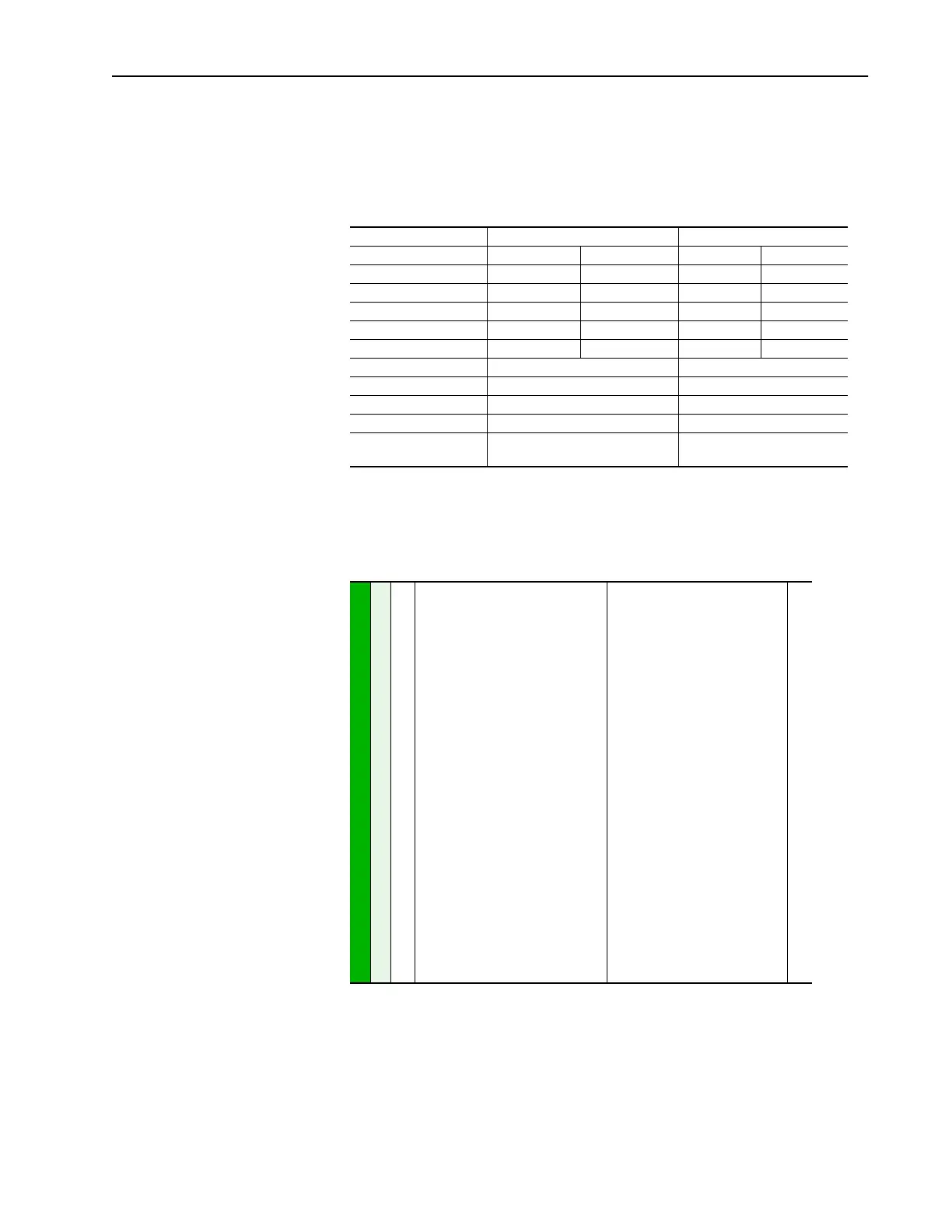
for a maximum of 250 VAC or 220 VDC. The table below shows
specifications and limits for each relay / contact.
Configuration
The outputs may be independently configured via the following parameters
to switch for various states of the drive.
The selections can be divided into three types of annunciation.
1. The relay changes state due to a particular status condition in the drive.
PowerFlex 70 PowerFlex 700
Resistive Load Inductive Load
Rated Voltage 250 VAC 250 VAC 250 VAC 250 VAC
220 VDC 220 VDC 220 VDC 220 VDC
Maximum Current 3 A 1.5 A 8 A 4 A
Maximum Power AC - 50 VA AC - 25 VA
DC - 60 W DC - 30 W
Minimum DC Current 10 µA
Minimum DC Voltage 10 mV
Switching Time 8ms 8ms
Initial State De-energized De-energized
Number of relays
(Standard I/O)
22
INPUTS & OUTPUTS
Digital Outputs
380
384
[Digital Out1 Sel]
[Digital Out2 Sel]
Selects the drive status that will energize
a (CRx) output relay.
(1)
Contacts shown on page 1-12 are in
drive powered state with condition not
present. For functions such as “Fault”
and “Alarm” the normal relay state is
energized and N.O. / N.C. contact wiring
may have to be reversed.
Default:
Options:
1
4
1
2
3
4
5
6
7
8
9
10
11
12
13
14
15
16
17
18
19
20
21
22
23
24
25
26
“Fault”
“Run”
“Fault”
(1)
“Alarm”
(1)
“Ready”
“Run”
“Forward Run”
“Reverse Run”
“Auto Restart”
“Powerup Run”
“At Speed”
“At Freq”
“At Current”
“At Torque”
“At Temp”
“At Bus Volts”
“At PI Error”
“DC Braking”
“Curr Limit”
“Economize”
“Motor Overld”
“Power Loss”
“Input 1 Link”
“Input 2 Link”
“Input 3 Link”
“Input 4 Link”
“Input 5 Link”
“Input 6 Link”
381
385
382
386
383
002
001
003
004
218
012
137
157
147
053
048
184

 Loading...


