2-64 Digital Outputs
The following drive conditions or status can be selected to cause the
relay activation:
2. The relay changes state because a particular value in the drive has
exceeded a preset limit.
The following drive values can be selected to cause the relay activation:
The balance of these functions require that the user set a limit for the
specified value. The limit is set into one of two parameters: [Dig Out1
Level] and [Dig Out2 Level] depending on the output being used. If the
value for the specified function (frequency, current, etc.) exceeds the user
programmed limit, the relay will activate. If the value falls back below
the limit, the relay will deactivate.
Notice that the [Dig Outx Level] parameters do not have units. The drive
assumes the units from the selection for the annunciated value. For
example, if the chosen “driver” is current, the drive assumes that the
entered value for the limit [Dig Outx Level] is% rated Amps. If the
Condition Description
Fault A drive Fault has occurred and stopped the drive
Alarm A Drive Type 1 or Type 2 Alarm condition exists
Ready The drive is powered, Enabled and no Start Inhibits exist. It is “ready” to
run
Run The drive is outputting Voltage and frequency to the motor (indicates 3–
wire control, either direction)
Forward Run The drive is outputting Voltage and frequency to the motor (indicates 2–
wire control in Forward)
Reverse Run The drive is outputting Voltage and frequency to the motor (indicates 2–
wire control in Reverse)
Reset/Run The drive is currently attempting the routine to clear a fault and restart
the drive
Powerup Run The drive is currently executing the Auto Restart or “Run at Power Up”
function
DC Braking The drive is currently executing either a “DC Brake” or a “Ramp to Hold”
Stop command and the DC braking voltage is still being applied to the
motor.
Current Limit The drive is currently limiting output current
Economize The drive is currently reducing the output voltage to the motor to
attempt to reduce energy costs during a lightly loaded situation.
Mtr Overload The drive output currenthas exceeded the programmed [Motor NP FLA]
and the electronic motor overload function is accumulating towards an
eventual trip.
Power Loss The drive has monitored DC bus voltage and sensed a loss of input AC
power that caused the DC bus voltage to fall below the fixed monitoring
value (82% of [DC bus Memory]
Condition Description
At Speed The drive Output Frequency has equalled the commanded frequency
381
385
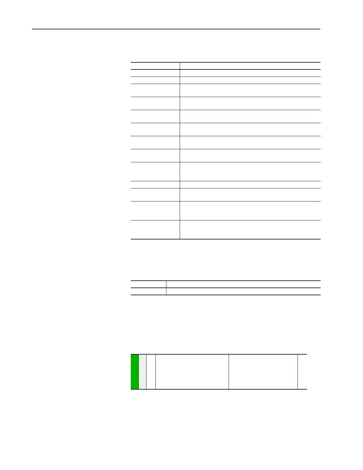
[Dig Out1 Level]
[Dig Out2 Level]
Sets the relay activation level for options
10 – 15 in [Digital Outx Sel]. Units are
assumed to match the above selection
(i.e. “At Freq” = Hz, “At Torque” = Amps).
Default:
Min/Max:
Display:
0.0
0.0
0.0/819.2
0.1
380

 Loading...


