2-86 Grounding, General
Grounding, General The drive Safety Ground - PE must be connected to system ground. Ground
impedance must conform to the requirements of national and local
industrial safety regulations and/or electrical codes. The integrity of all
ground connections should be periodically checked.
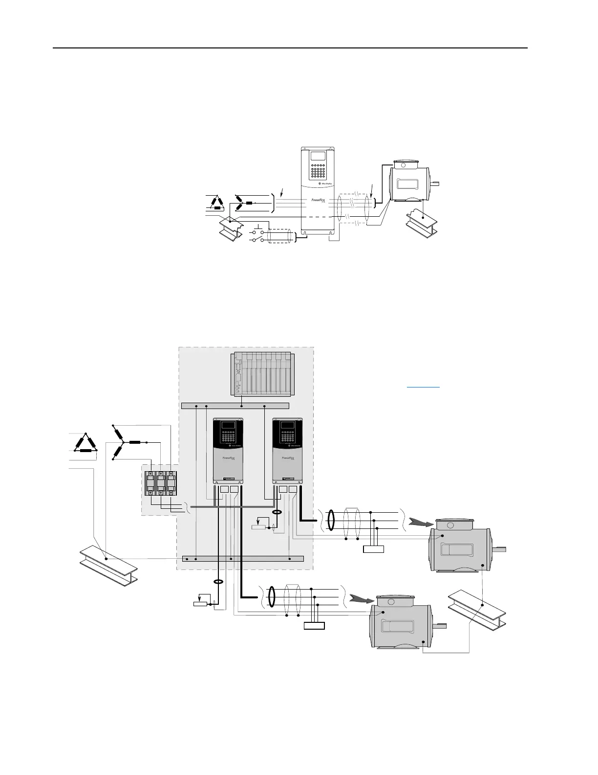
Figure 2.11 Typical Grounding
For installations within a cabinet, a single safety ground point or ground bus
bar connected directly to building steel should be used. All circuits
including the AC input ground conductor should be grounded
independently and directly to this point/bar.
Figure 2.12 Single-Point Grounding/Panel Layout
U (T1)
V (T2)
W (T3)
R (L1)
S (L2)
T (L3)
PE
SHLD
R (L1)
S (L2)
T (L3)
PE
PWR
STS
PORT
MOD
NET A
NET B
PWR
STS
PORT
MOD
NET A
NET B
U (T1)
V (T2)
W (T3)
TE
PE
U (T1)
V (T2)
W (T3)
TE
➊
➎
➌
➍
➋
➒
➐
➏
➑
➎
➏
➐
➒
➓
➓
Refer to page 2-87 for an
explanation of numbered items.

 Loading...


