2-46 Digital Inputs
Digital Inputs Cable Selection
Important points to remember about I/O wiring:
• Always use copper wire.
• Wire with an insulation rating of 600V or greater is recommended.
• Control and signal wires should be separated from power wires by at
least 0.3 meters (1 foot).
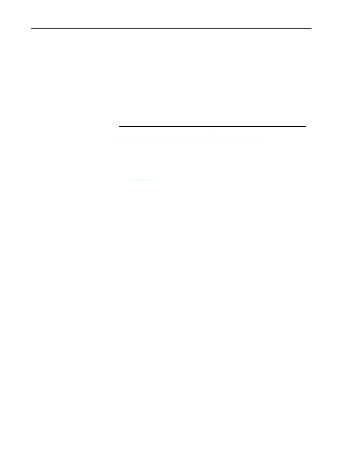
Table 2.J Recommended Control Wire for Digital I/O
Wiring Examples
See page 2-17.
There are 6 digital (discrete) inputs (numbered 1 through 6) available at the
terminal block.
PowerFlex 70
Each digital input has a maximum response/pass through/function
execution time of 25ms. For example, no more than 25ms should elapse
from the time the level changes at the Start input to the time voltage is
applied to the motor.
There is both hardware and software filtering on these inputs. The hardware
provides an average delay of 12ms from the time the level changes at the
input to the earliest time that the software can detect the change. The actual
time can vary between boards from 7 to 17ms, but any particular board
should be consistent to within 1% of its average value. The amount of
software filtering is not alterable by the user.
PowerFlex 700
Each digital input has a maximum response/pass through/function
execution time of 25ms. This means that, for example, no more than 25ms
should elapse from the time the level changes at the Start input to the time
voltage is applied to the motor.
Digital Input Configuration
Inputs are configured for the required function by setting a [Digital Inx Sel]
parameter (one for each input). These parameters cannot be changed while
the drive is running.
Type Wire Type(s) Description
Minimum
Insulation Rating
Unshielded Per US NEC or applicable
national or local code
– 300V, 60 degrees C
(140 degrees F)
Shielded Multi-conductor shielded cable
such as Belden 8770(or equiv.)
0.750 mm
2
(18AWG), 3
conductor, shielded.

 Loading...


