Analog Inputs 2-17
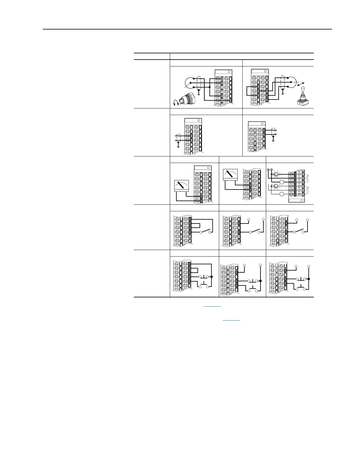
I/O Wiring Examples (PowerFlex 700 shown)
Input/Output Connection Example
(3)
(3)
Examples show hardware wiring only. Refer to page 2-16 for parameters that must be adjusted.
Potentiometer
(1)
10k Ohm Pot.
Recommended
(2k Ohm Minimum)
Joystick
(1)
±10V Input - 100k
ohm input
impedance.
(1)
Refer to the Attention statement on page 2-15 for important bipolar wiring information.
Potentiometer Joystick
Analog Input
±10V Input - 100k
ohm input
impedance.
4-20 mA Input- 100
ohm input
impedance
Voltage - Bipolar
(1)
Current - Unipolar
Analog/Digital
Output
±10V Output - Can
drive a 10k ohm
load (25 mA short
circuit current limit).
Voltage Current Logic
2 Wire Control
(2)
-
Non-Reversing
Requires 2-wire
functions only ([Dig-
ital In1 Sel]). Using
3-wire selections
will cause a type 2
alarm.
(2)
Important: Programming inputs for 2 wire control deactivates all HIM Start buttons.
24VDC Internal Supply
(4)
(4)
If desired, a User Supplied 24V DC power source can be used. Refer to the “External” example.
24VDC External Supply 115V External Source
3 Wire Control
Requires only
3-wire functions
([Digital In1 Sel]).
Including 2-wire
selections will
cause a type 2
alarm.
24VDC Internal Supply
(4)
24VDC External Supply 115V External Source
1
2
5
22
3
5
21
22
3
4
17
18
–
+
6
7
+ –
8
9
+ –
Power Source
11
12
13
14
15
16
or
24
25
26
27
Stop-Run
25
27
Stop-Run
+24V
Common
25
27
Stop-Run
Neutral 115V
Start
24
25
26
27
28
Stop
Start
25
27
28
Stop
+24V
Common
Start
115VNeutral
Stop
25
27
28

 Loading...


