2-16 Analog Inputs
Refer to Table 2.J on page 2-46 for recommended digital I/O control wire.
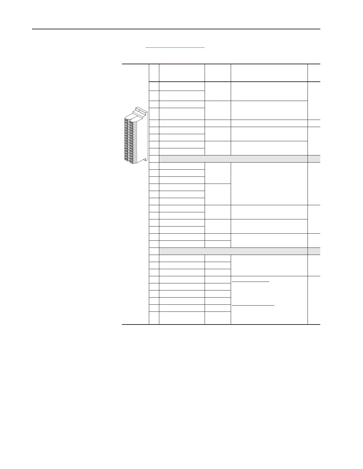
Figure 2.1 PowerFlex 700 Standard I/O Terminal Designations
Refer to the PowerFlex 70 User Manual for terminal designations and
wiring examples.
No. Signal
Factory
Default
Description
Related
Param.
1 Anlg Volts In 1 (–)
(1)
(1)
These inputs/outputs are dependant on a number of parameters. See “Related Parameters.”
Isolated
(2)
, bipolar, differential, ±10V,
11 bit & sign, 100k ohm input
impedance.
(2)
Differential Isolation - External source must be maintained at less than 160V with respect to PE. Input provides
high common mode immunity.
320 -
329
2 Anlg Volts In 1 (+)
3 Anlg Volts In 2 (–)
(1)
Isolated
(3)
, bipolar, differential, ±10V,
11 bit & sign, 100k ohm input
impedance.
(3)
Differential Isolation - External source must be less than 10V with respect to PE.
4 Anlg Volts In 2 (+)
5 Pot Common – For (+) and (–) 10V pot references.
6 Anlg Volts Out 1 (–)
(1)
Bipolar, differential, ±10V, 11 bit &
sign, 2k ohm minimum load.
338 -
346
7 Anlg Volts Out 1 (+)
8 Anlg Current Out 1 (–)
(1)
4-20mA, 11 bit & sign, 500 ohm
maximum load.
9 Anlg Current Out 1 (+)
10
Reserved for Future Use
11 Digital Out 1 – N.C. Fault Resistive Load
Rating: 8A at 250V AC/30V DC
Min. Load: 10mA
Inductive Load
Rating: 2A at 250V AC/30V DC
Min. Load: 10mA
380 -
387
12 Digital Out 1 Common
13 Digital Out 1 – N.O.
14 Digital Out 2 – N.C. Alarm
15 Digital Out 2 Common
16 Digital Out 2 – N.O.
17 Anlg Current In 1 (–)
(1)
Isolated
(2)
,
4-20mA
, 11 bit & sign, 100
ohm input
impedance.
320 -
329
18 Anlg Current In 1 (+)
19 Anlg Current In 2 (–)
(1)
Isolated
(3)
, 4-20mA, 11 bit & sign, 100
ohm input impedance.
20 Anlg Current In 2 (+)
21 –10V Pot Reference – 2k ohm minimum, 15mA maximum
load.
22 +10V Pot Reference –
23
Reserved for Future Use
24 +24VDC – Drive supplied power for logic inputs.
150mA maximum Load.
25 Digital In Common –
26 24V Common –
27 Digital In 1 Stop - CF
115V AC, 50/60 Hz
Opto isolated (250V)
Low State: less than 30V AC
High State: greater than 100V AC
24V AC/DC, 50/60 Hz
Opto isolated (250V)
Low State: less than 5V AC
High State: greater than 20V AC
361 -
366
28 Digital In 2 Start
29 Digital In 3 Jog
30 Digital In 4 Speed Sel 1
31 Digital In 5 Speed Sel 2
32 Digital In 6 Speed Sel 3
1
16
32

 Loading...


