2-30 Cable, Control
PowerFlex 70
In PowerFlex 70, the user selects the bus voltage regulator using the [Bus
Reg Mode A] and [Bus Reg Mode B] parameters. The available modes
include “Disabled,” “Adjust Freq,” and “Dynamic brak.” The bus voltage
regulator is never active with the internal dynamic braking function.
The bus voltage regulation set point Vreg in PowerFlex 70 is fixed for each
voltage class of drive. The bus voltage regulation set points are identical to
the internal dynamic brake regulation set points V
DB’s
and are shown in
Table 2.E.
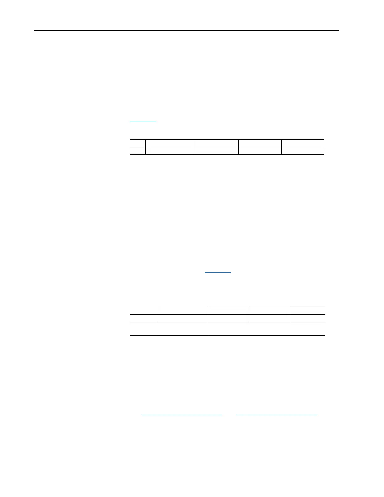
Table 2.E PowerFlex 70 Bus Voltage Regulation Set Points (Vreg)
The nature of this control is to increase the magnitude of the drive’s output
frequency to reduce or eliminate regeneration and avoid an over-voltage
fault. The increase in output frequency may increase the operating voltage.
The magnitude increase in frequency when bus regulation is active is
limited to the sum of [Maximum Speed] and [Overspeed Limit]. When this
frequency limit is met, the output frequency will be clamped and an
over-voltage fault occurs if regeneration continues to increase the bus
voltage.
PowerFlex 700
PowerFlex 700 allows the user to simultaneously enable both internal
dynamic braking and the bus voltage regulator. There are two bus voltage
regulation set point parameters, [Bus Reg Mode A] and [Bus Reg Mode B]
in the PowerFlex 700 (See
Table 2.F). The user can select which bus
regulation set point is active by configuring one of the digital inputs as a
selector.
Table 2.F PowerFlex 700 Dynamic Braking and Bus Voltage Limit References
The nature of this control, like PowerFlex 70, is to increase the magnitude
of the drive’s output frequency to reduce or eliminate regeneration and
avoid a bus over-voltage fault. The increase in the output frequency may
increase the operating voltage. PowerFlex 700 internally limits the
magnitude of output frequency to the sum of Maximum Speed and
Overspeed Limit.
Cable, Control See Cable Selection on page 2-15 and Cable Selection on page 2-46.
Cable Entry Plate
Removal
If additional wiring access is needed, the Cable Entry Plate on 0-3 Frame
drives can be removed. Simply loosen the screws securing the plate to the
chassis. The slotted mounting holes assure easy removal.
200/240 V Class Drive 400 V Class Drive 480 V Class Drive 600 V Class
V
reg
377 VDC 750 VDC 750 VDC –
200/240 V Class Drive 400 V Class Drive 480 V Class Drive 600 V Class
V
db
377 VDC 750 VDC 750 VDC –
Bus Reg 1
Bus Reg 2
358 – 392 VDC 715 – 785 VDC 715 – 785 VDC –

 Loading...


