Alarms 2-3
The configuration bits act as a mask to block or pass through the alarm
condition to the active condition. An active alarm will be indicated on the
LCD HIM and will cause the drive alarm status bit to go high (“1”) in the
Drive Status word (Bit 6, parameter 209). This bit can then be linked to a
digital output for external annunciation. As default, all configuration bits
are high (“1”). Note that setting a configuration bit to “0” to “mask” an
alarm does not affect the status bit in the Drive Alarm parameter, only its
ability to annunciate the condition.
Application
A process is being controlled by a PowerFlex drive. The speed reference to
the drive is a 4 –20 mA analog signal from a sensor wired to Analog Input
1.
The input is configured for mA by setting the corresponding bit in [Anlg In
Config] to “1”
The input is scaled for 4-20 mA by setting [Analog In 1 Lo] to “4” mA and
[Analog In 1 Hi] to “20” mA.
The signal is designated as the active speed reference by setting [Speed Ref
A Sel] to its factory default value of “1”
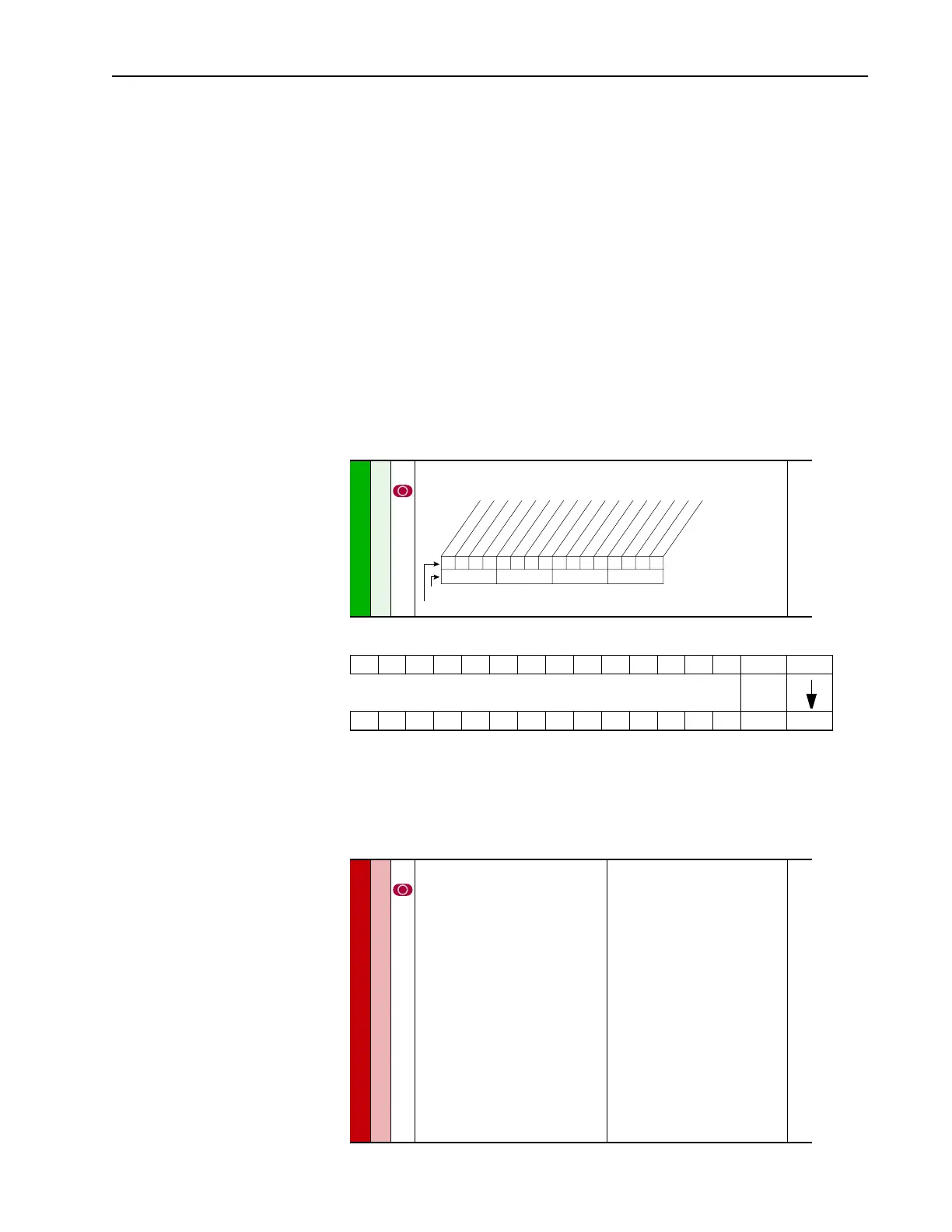
320 [Anlg In Config]
Selects the mode for the analog inputs.
322
325
323
326
Analog In Config
01
Speed Ref A Sel
1
Speed References
090 [Speed Ref A Sel]
Selects the source of the speed
reference to the drive unless [Speed Ref
B Sel] or [Preset Speed 1-7] is selected.
(1)
See Appendix B for DPI port locations.
Default:
Options:
2
1
2
3-8
9
10
11
12
13
14
15
16
17
18
19
20
21
22
23
“Analog In 2”
“Analog In 1”
“Analog In 2”
“Reserved”
“MOP Level”
“Reserved”
“Preset Spd1”
“Preset Spd2”
“Preset Spd3”
“Preset Spd4”
“Preset Spd5”
“Preset Spd6”
“Preset Spd7”
“DPI Port 1”
(1)
“DPI Port 2”
(1)
“DPI Port 3”
(1)
“DPI Port 4”
(1)
“DPI Port 5”
(1)
“DPI Port 6”
(1)
002
091
thru
093
101
thru
107
117
thru
120
192
thru
194
213
272
273
320
361
thru
366
0xx 0xxxxxxxxxxxx
10 01234567891112131415
1=Current
0=Voltage
x =Reserved
Bit #
Factory Default Bit Values
A
na
log
In 1
A
n
alo
g In
2

 Loading...


