Installation
19
4" Color Touch Panels with Audio
12. Make sure to align the Light, IR receiver, and PIR Motion sensor locations to their respective
openings on the front bezel/faceplate. Make sure the buttons are flush against the faceplate.
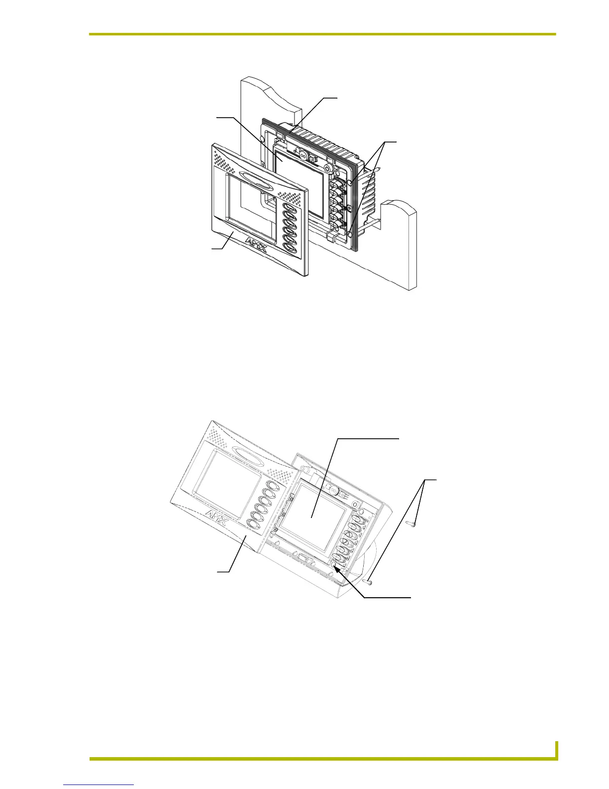
Removing the AXT Faceplate/Bezel
Whereas the AXD faceplate is removable by gripping the faceplate from the notches and pulling
outwards, the AXT faceplate is secured to the enclosure via four (4) #4-40 phillips-head screws
located along the rear corners of the panel (FIG. 18).
1. Flip the AXT panel over and place the LCD onto a soft cloth to prevent scratching during the
removal process.
2. Locate the four (4) phillips-head #4-20 screws on the rear of the enclosure.
3. Remove the screws by inserting a grounded Phillips screwdriver into the screw holes and turn
the screws counter-clockwise.
FIG. 17 Foam insulation location on a solid surface mounted AXD
FIG. 18 AXT faceplate removal and screw locations
4 - #4-40 solid
surface screws
A - Faceplate
(bezel)
B - Main unit
(with LCD)
Foam Insulation strip
B - Main AXT unit consists of
Remove/Install the four (4)
#4-20 screws from/into the
location indicated
the touch panel, internal components
A - Faceplate
(bezel)
and enclosure
Securing screws (4) #4-20
 Loading...