Designing Touch Panel Pages
37
4" Color Touch Panels with Audio
of the light sensor. The LEDs also illuminate if there is no PIR activity and the light
sensor level falls below its threshold value.
The order of precedence for turning Off the pushbutton LEDs is the LS then PIR. If
the light sensor rises above its hysteresis (turn-on) value and there is no any activity
coming from the PIR (thirty seconds of inactivity), the LEDs turn Off.
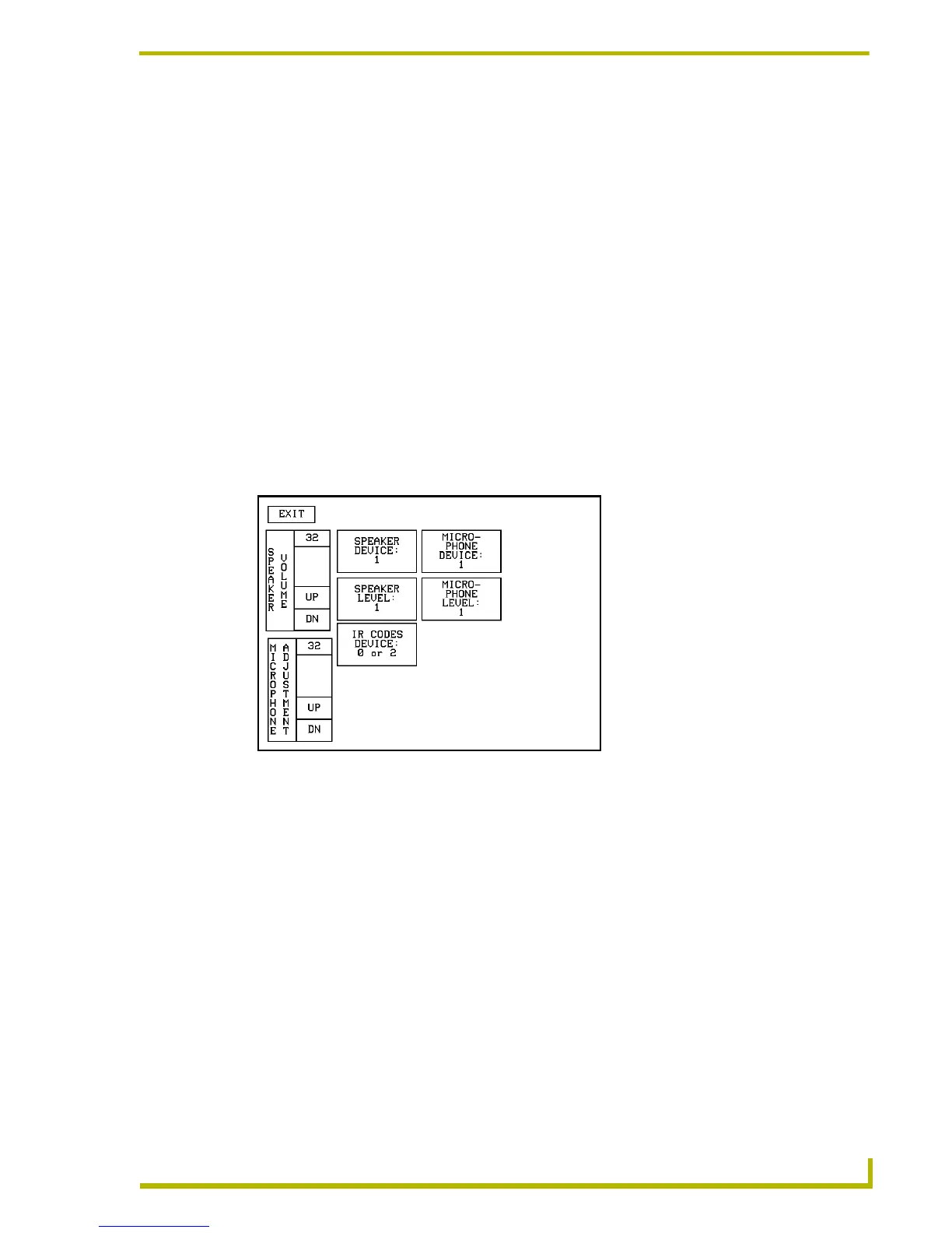
Using the Audio and IR Device Setup page
The speaker volume control, microphone control, and the IR device codes will be facilitated
through a Audio And IR Device Setup Page. This page is used to configure the various features and
parameters for the CP4/A panel sensors. To access the Sensors Setup page:
1. From the Main page press the
SETUP button.
2. Press
ADJUST SENSORS from the Setup page (FIG. 26 on page 29).
3. Press
AUDIO AND IR DEVICE SETUP from the Adjust Sensors page (FIG. 30 on page 34).
4. Choose from any of these buttons and sliders to alter and set the properties for the speakers, IR
receiver, and microphone (FIG. 31 on page 37).
SPEAKER VOLUME allows the user to adjust the effective speaker volume. The panel
consists of an up button (UP), a down button (DN), and a current setting indicator (range
is between 0 and 32). The Speaker Volume up and down buttons adjust the Speaker
Volume. A zero value will mute the speaker. An adjustment to the speaker volume is also
achieved through the use of the SVOL AXlink Send_Command. Refer to page 50 for
more information.
MICROPHONE ADJUSTMENT allows the user to adjust the effective microphone
volume. The panel consists of an up button (UP), a down button (DN), and a current
setting indicator (range is between 0 and 32). The Microphone Adjustment up and down
buttons adjust the Microphone Volume. A zero value will mute the microphone. An
adjustment to the speaker volume is also achieved through the use of the MVOL AXlink
Send_Command. Refer to page 48 for more information.
FIG. 31 Adjust Sensors page
 Loading...