Installation
22
4" Color Touch Panels with Audio
Wiring the CP4/A terminal connectors and cables
You will need a wire stripper and Phillips screwdriver to prepare and connect the captive wires.
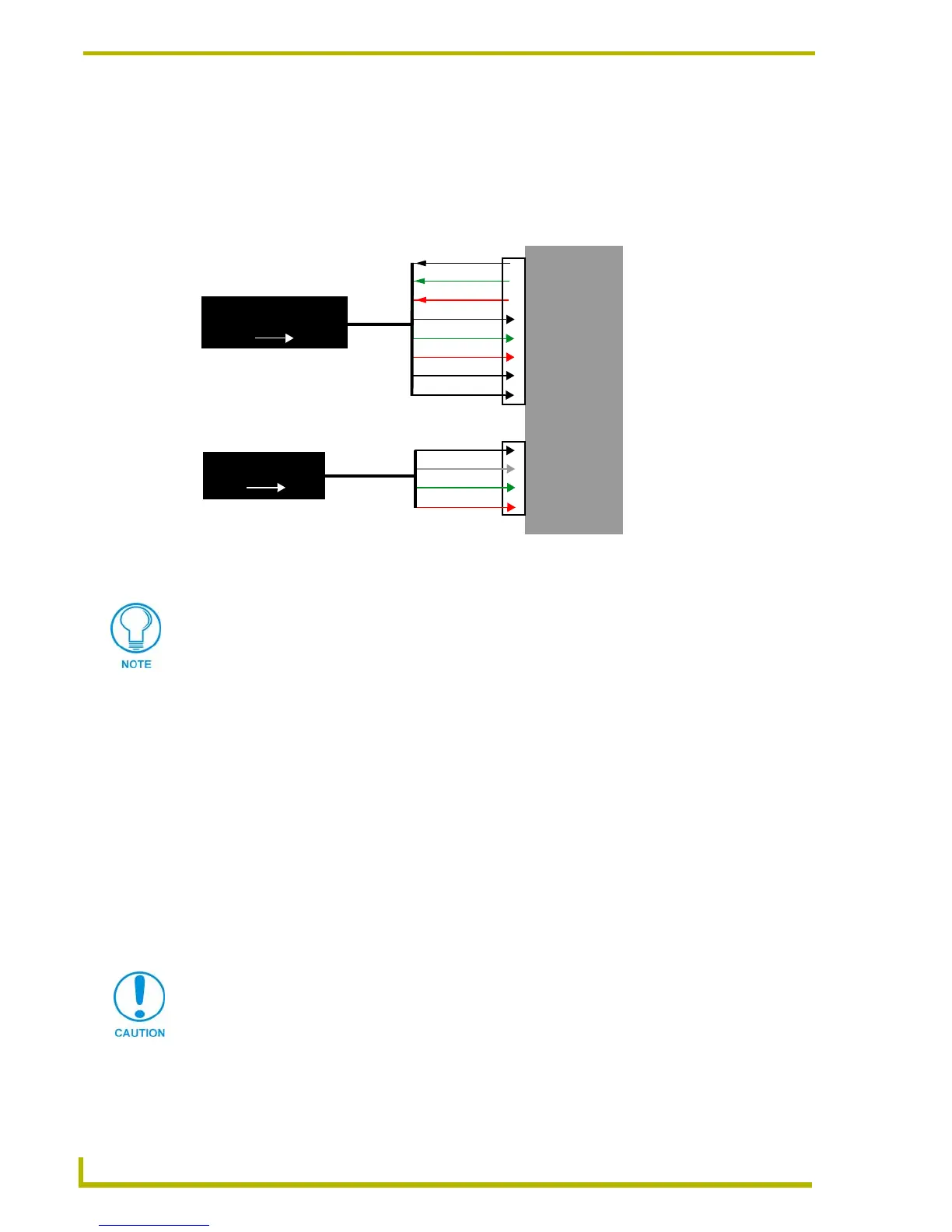
Power and Audio connectors are wired and attached to the rear of the CP4/A. FIG. 21 provides a
layout of the wiring connection into both the AXD and AXT touch panels. This diagram is intended
for use in wiring the terminal ends of the 4-pin and 8-pin cables.
1. Loosen the screws on both the 4-pin and 8-pin connectors before insertion.
2. Strip 0.25 inch of wire insulation off all wires.
3. Insert the incoming PWR, AXP, AXM, and GND wires from the Controller’s AXlink
connector into the respective openings on the terminal 4-pin 3.5 mm mini-Phoenix AXlink
connector locations shown in FIG. 21.
4. Insert the outgoing microphone and incoming audio wires from the existing audio system into
the respective openings on the terminal 8-pin 3.5 mm mini-Phoenix audio connector locations
shown in FIG. 21.
5. Secure the connections by using a grounded Phillips screwdriver to turn the screws clockwise.
Do not over-torque the screws; doing so can bend the seating pin and damage the connector.
6. Insert the wired connectors to the rear of the CP4/A touch panel.
7. Unscrew the two (2) screws that attach the clip to the underside of the AXT.
8. Thread the tabletop cable through the cable-clip opening at the rear of the AXT unit
(FIG. 20 on page 21).
FIG. 21 CP4/A terminal connector pinout and wiring diagram
AXD/T-CP4/A
Microphone (-)
Audio Right (-)
Audio GND
GND
AXM
PWR
Microphone (+)
Mic GND
Audio Right (+)
4-pin
3.5 mm mini-AXlink
8-pin
3.5 mm Audio Connector
AXP
Audio Left (+)
Audio Left (-)
Touch
Panel
Rear
Front
Terminal connections are
dependent on the system configuration
On an AXT-CP4/A panel, these terminal connections are already wired to the
appropriate connectors. To wire the terminal end of the AXT panel, connect the
connectors to the rear of the panel as shown in FIG. 21 and thread the tabletop cable
(CA5921-01) through the cable support clip located at the base of the panel (rear).
Do not connect power to the touch panel until wiring is complete. If you are using a
12 VDC power supply, apply power to the touch panel only after installation is
complete.
 Loading...