Upgrading the Firmware
68
4" Color Touch Panels with Audio
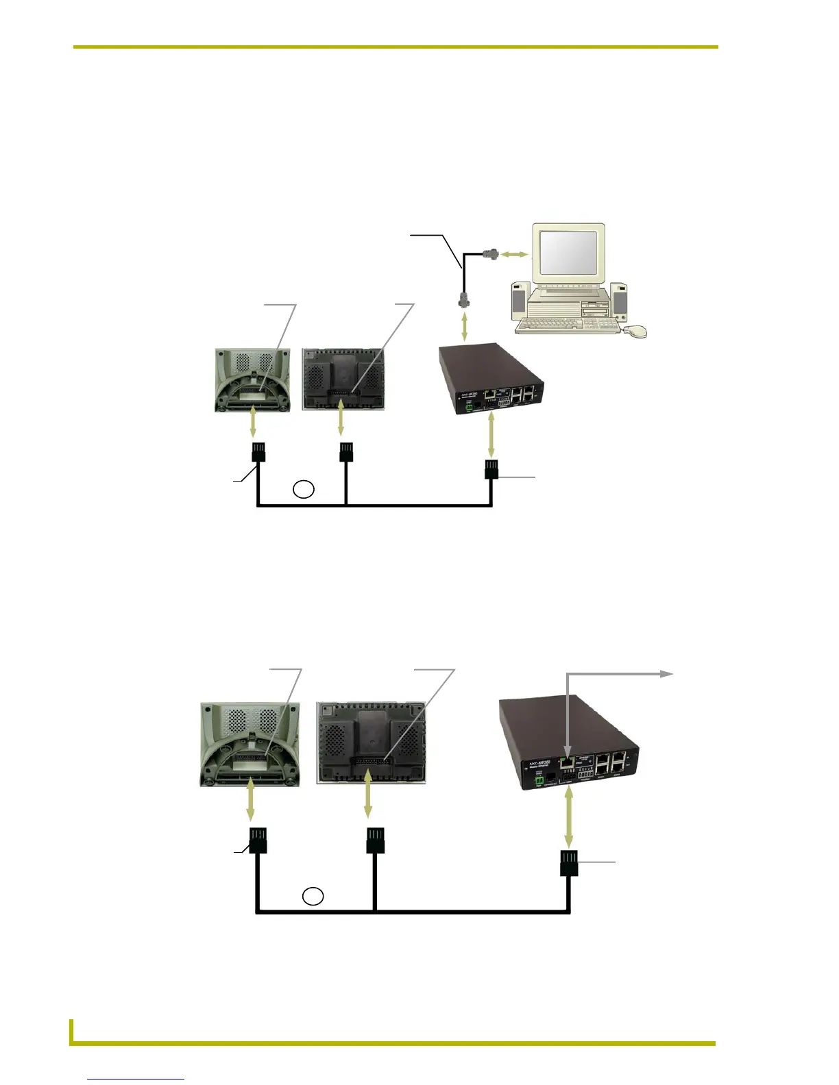
RS-232 via the Master (FIG. 33): In this method, a user connects one end of the optional
Axcess programming cable (FG10-727) DB9 female to the Program port (male) on the
from of the Master and the other DB9 female end to the PC’s rear male COM port.
A 4-pin mini-AXlink connector is then used to bridge the gap from the rear AXlink port
on the Master to the rear AXlink port on the CP4/A panel.
AXlink via the Master (FIG. 33): In this method, a user connects one end of a 4-pin
mini-AXlink cable to the Master (either to its corresponding AXlink connector or to an
AXlink bus strip feeding signals to the Master) and the other end of the mini-AXlink
connector cable to the AXlink port (female) on the rear of the CP4/A panel. In this case,
the Master is connected to a PC via Ethernet.
FIG. 33 CP4/A communication - RS-232 from PC to Master - mini-AXlink from Master to panels
FIG. 34 CP4/A communication - Ethernet from PC to Master - mini-AXlink from Master to panels
Central Controller/Master
AXT 4-pin AXlink
4-pin
port (female)
AXD 4-pin AXlink
port (female)
mini-AXlink
or
connector
(male)
4-pin
mini-AXlink
connector
(male)
Axcess Programming
goes from the Master Program
Port (front) to the PC’s rear RS-232
cable - FG10-727
male COM port
(connection made at AXlink port)
AXT 4-pin AXlink
4-pin
port (female)
AXD 4-pin AXlink
port (female)
mini-AXlink
or
Central Controller
PC to Master via Ethernet
connector
(male)
4-pin
mini-AXlink
connector
(male)
 Loading...