2.8 USB 2.0 and Ethernet static memory interface
The FPGA incorporates a simple Static Memory Controller (SMC) that interfaces to the USB 2.0 and
Ethernet controllers on the MPS3 board.
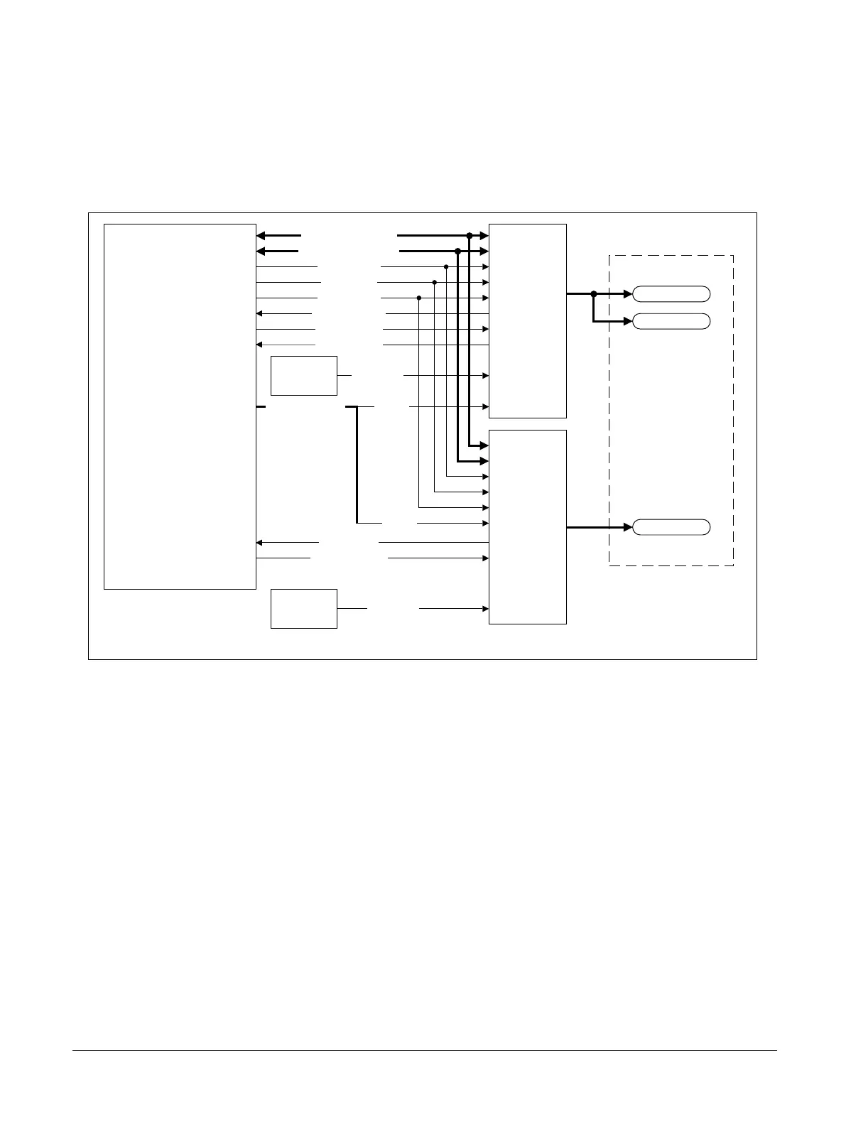
The following figure shows the USB 2.0 and Ethernet SMC interface.
MPS3 FPGA Prototyping Board
FPGA
USB 2.0
controller
ISP 1763
USB 2.0
Ethernet
controller
LAN9220
SMBF_ADDR[6:0]
SMBF_DATA[15:0]
SMB_nRST
SMB_nOE
SMB_nWE
USB_nHCINT
USB_DACK
USB_DREQ
ETH_INTR
ETH_FIFOSEL
OSC3A
USB REF
12MHZ
OSC4
ETH REF
25MHZ
SMBF_CS[1:0] CS[1]
CS[0]
USB 2.0
Ethernet
Combined Ethernet and
dual-USB 2.0 connector
(J2)
Figure 2-13 MPS3 board USB 2.0 and Ethernet static memory interface
Related information
A.6 Combined Ethernet and dual USB-A connector on page Appx-A-84
1.3 Location of components on the MPS3 board on page 1-15
2 Hardware description
2.8 USB 2.0 and Ethernet static memory interface
100765_0000_04_en Copyright © 2017–2020 Arm Limited or its affiliates. All rights
reserved.
2-35
Non-Confidential
 Loading...
