EasyManua.ls Logo

ARM MPS3 User Manual

Default Icon
92 pages
To Next Page IconTo Next Page
To Previous Page IconTo Previous Page
Page #53 background imageLoading...
Page #53 background image
2.19 Design settings for correct board operation with a minimal design
For correct operation with a minimal design, the MPS3 board requires a minimum amount of RTL in the
FPGA, and certain variable settings in the config.txt file.
Minimum RTL
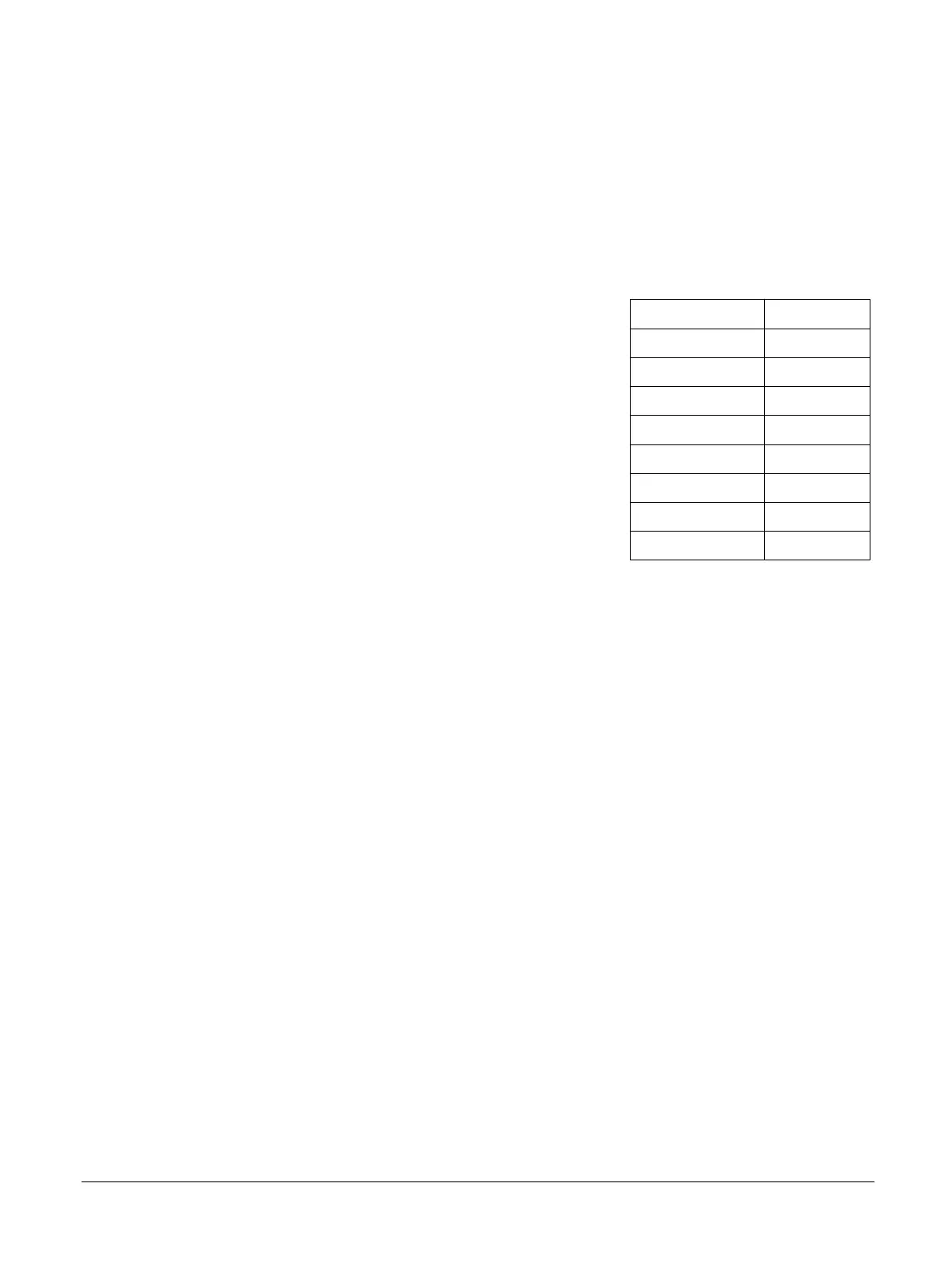
The following table shows the signals that you must tie off in the FPGA to generate the
minimum RTL for correct operation of the MPS3 board.
Table 2-3 Minimum RTL for correct operation of the MPS3 board
FPGA signal Minimum RTL
MMB_IDCLK Tie LOW
EMMC_CLK Tie LOW
QSPI_nCS Tie HIGH
QSPI_SCLK Tie LOW
IOFPGA_SYSWDT Tie LOW
WDOG_RREQ Tie LOW
SMBM_nWAIT Tie HIGH
CFG_DATAOUT Tie LOW
Configuration file settings
If the design does not implement the Serial Configuration Controller (SCC), you must set the
variable FPGA_SCC to FALSE in the board config.txt file.
If the design does not implement the MCCSMC interface, you must set the variable
FPGA_SMB to FALSE in the board config.txt file.
See 3.5.2 config.txt generic board configuration file on page 3-64.
2 Hardware description
2.19 Design settings for correct board operation with a minimal design
100765_0000_04_en Copyright © 2017–2020 Arm Limited or its affiliates. All rights
reserved.
2-53
Non-Confidential

Other manuals for ARM MPS3

Question and Answer IconNeed help?

Do you have a question about the ARM MPS3 and is the answer not in the manual?

ARM MPS3 Specifications

General IconGeneral
BrandARM
ModelMPS3
CategoryMotherboard
LanguageEnglish

Summary

Preface

About this book

Describes the book's purpose, audience, structure, glossary, and conventions.

Feedback

Instructions for providing comments and suggestions about the product and content.

Introduction

Precautions

Safety and damage prevention advice for using the MPS3 board.

About the MPS3 board

Details the MPS3 board's features, uses, and major components.

Location of components on the MPS3 board

Illustrates the physical layout and placement of components on the MPS3 board.

Hardware description

Overview of the board hardware

Introduces the MPS3 board's FPGA and peripheral infrastructure.

Example Cortex®-M33 IoT Kit subsystem design

Presents a reference design for the MPS3 board's IoT kit subsystem.

Clocks

Describes the fixed and programmable clock sources for the MPS3 board.

Reset, powerup, and configuration

Explains the board's reset system and powerup sequencing.

Power

Details how to supply power to the MPS3 board and its specifications.

Serial Configuration Controller interface

Describes the SCC interface for configuring the FPGA via the MCC.

MCC-SMC interface

Explains the interface between the MCC and the FPGA's Static Memory Controller.

USB 2.0 and Ethernet static memory interface

Details the SMC interface for USB 2.0 and Ethernet controllers.

Video HDLCD interface

Describes the implementation of an HDLCD interface using the HDMI connector.

Audio codec interface

Explains the stereo audio interface with Line In, Line Out, and Mic In.

QVGA video CLCD display

Details the on-board CLCD display panel and its interface.

On-board user components

Describes the user LEDs, switches, and push buttons connected to the FPGA.

Interrupts

Lists peripheral interrupt signals connecting to external FPGA pins.

FPGA DDR4 memory interface

Details the 4GB DDR4 SODIMM and its interface to the FPGA.

User non-volatile memory

Describes the QSPI flash, eMMC, and microSD card interfaces.

Arduino Shield and Pmod interfaces

Explains the two Shield and four Pmod expansion interfaces.

FMC-HPC interface

Covers high-speed expansion using the FMC-HPC standard connector.

System debug

Details various methods for performing debug and trace on the MPS3 board.

Design settings for correct board operation with a minimal design

Specifies minimum RTL and configuration settings for minimal board operation.

Configuration

Overview of the configuration system

Explains the Motherboard Configuration Controller's role in board setup.

Remote USB operation

Describes how to control the MCC remotely via the Debug USB port.

Powerup and configuration sequence

Details the sequence of events during board powerup and configuration.

Reset push buttons

Explains the function of software (PBON) and hardware (PBRST) reset buttons.

Configuration files

Describes configuration files and microSD card directory structure.

MCC command-line interface

Details system command-line input to the MCC via UART.

Signal descriptions

Debug connectors

Lists connectors for processor debug, FPGA debug, trace, and SWD.

Arduino Shield connectors

Describes the two Shield expansion interfaces with digital and analog I/O.

Peripheral Module (Pmod) connectors

Details the four Pmod connectors for digital I/O expansion.

FMC-HPC connector

Covers the 400-way connector for FMC expansion boards.

FMC configuration connector

Describes the 14-pin connector for configuring Arm FMC boards.

Combined Ethernet and dual USB-A connector

Details the connector for Ethernet 10/100 and USB 2.0 controllers.

HDMI Type A female connector

Describes the connector for digital video and audio to external displays.

Audio connectors, stacked stereo jacks

Explains the three stereo jack connectors for audio input/output.

12V power connector

Details the DC power jack for connecting external power to the board.

Specifications

Available power for expansion boards

Lists maximum current the board can supply to expansion boards.

Revisions

Revisions

Lists technical changes between released issues of the document.

Related product manuals