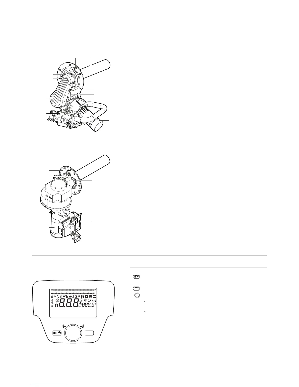
4.3.3 Main burner components
1 Burner door
2 Safety thermostat on the combustion chamber door
3 Burner
4 Flame inspection window
5 Ignition electrode
6 Air/gas inlet pipe
7 Gas valve
8 Ionisation probe
9 Fan
10 Venturi
1 Safety thermostat on the combustion chamber door
2 Burner
3 Burner door
4 Flue gas non-return valve
5 Venturi
6 Flame inspection window
7 Ignition electrode
8 Ionisation probe
9 Fan
10 Gas valve
4.4 Control panel description
4.4.1
Description of the keys
Shortcuts menu key
Quick access to the operating modes
Menu key
Selection and confirmation button
Rotary button for navigating between menu or parameter
screens
Push button to select a menu/parameter or to confirm a value/
action
Fig.13 Burner for POWER HT+ 1.130 and
POWER HT+ 1.150
Fig.14 Burner for POWER HT+ 1.200 and
POWER HT+ 1.250
MW-3000005
MENU
87654321 9 10 11 12 13 14 15 16 17 18 19 20 21 22 23 24
4 Description of the product
7702630 - v02 - 11082018 POWER HT + 25
 Loading...


