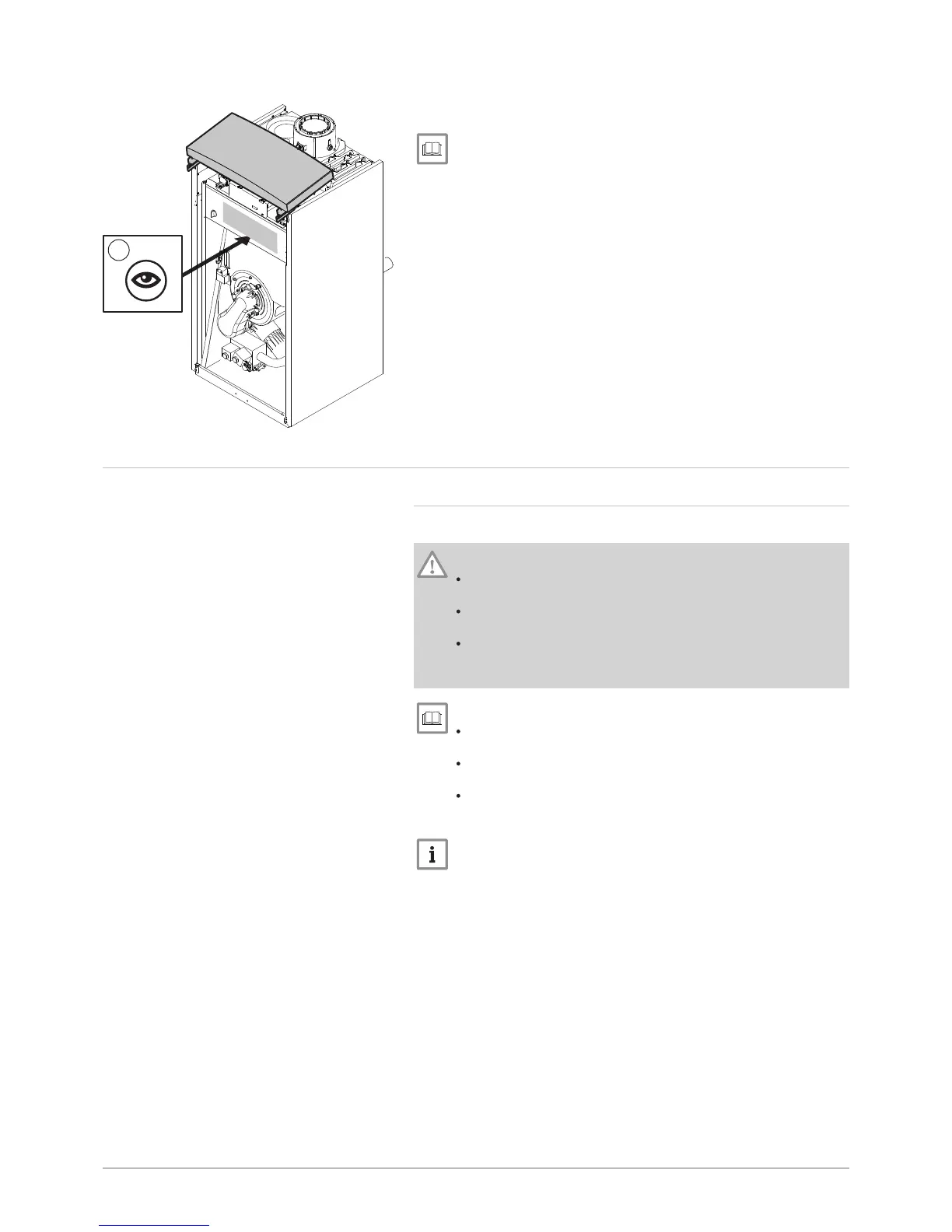
6. For POWER HT+ 1.130 and POWER HT+ 1.150 only: remove the
detachable panel if necessary.
See
The disassembly instructions can be found on the detachable
panel.
7.3
Hydraulic connections
7.3.1 Connecting the heating circuit
Respect the installations shown in the hydraulic diagrams.
Caution
The heating pipe must be mounted in accordance with the
provisions applicable.
If installing stop valves, position the fill/drain valve and the
expansion vessel between the stop valves and the boiler.
Always install a safety valve calibrated to 6 bar on the heating
circuit. The safety valve can be connected to a venting pot. The
safety valve must not be used to drain the heating circuit.
See
In the case of an assembly with a low-loss header, use the
assembly instructions for the low-loss header.
If using a cascade kit, use the assembly instructions for the
cascade kit.
If using an exchanger kit, use the assembly instructions for the
plate heat exchanger kit.
Important
The pipes are not provided.
Fig.62
 Loading...


