Tab.32 Authorised CO
2
ranges at maximum output
Boiler model Type G20 Type G25 Type G25.1 Type G27 Type G31
POWER HT+ 1.130 9.2 +0.2/- 0 9.2 +0.2/- 0 10.3 +0.2/-0 9.2 +0.2/-0 10 +0.2/- 0
POWER HT+ 1.150 9.2 +0.2/- 0 9.2 +0.2/- 0 10.3 +0.2/-0 9.2 +0.2/-0 10 +0.2/- 0
POWER HT+ 1.200 9.2 +0.2/- 0 9.2 +0.2/- 0 9.8 +0.3/-0 8.85 +0.2/-0 10.2 +0.2/- 0
POWER HT+ 1.250 8.85 +0.2/- 0 9.2 +0.2/- 0 9.8 +0.3/-0 8.85 +0.2/-0 10.2 +0.2/- 0
8.4.3
Setting the air/gas ratio (reduced heat input)
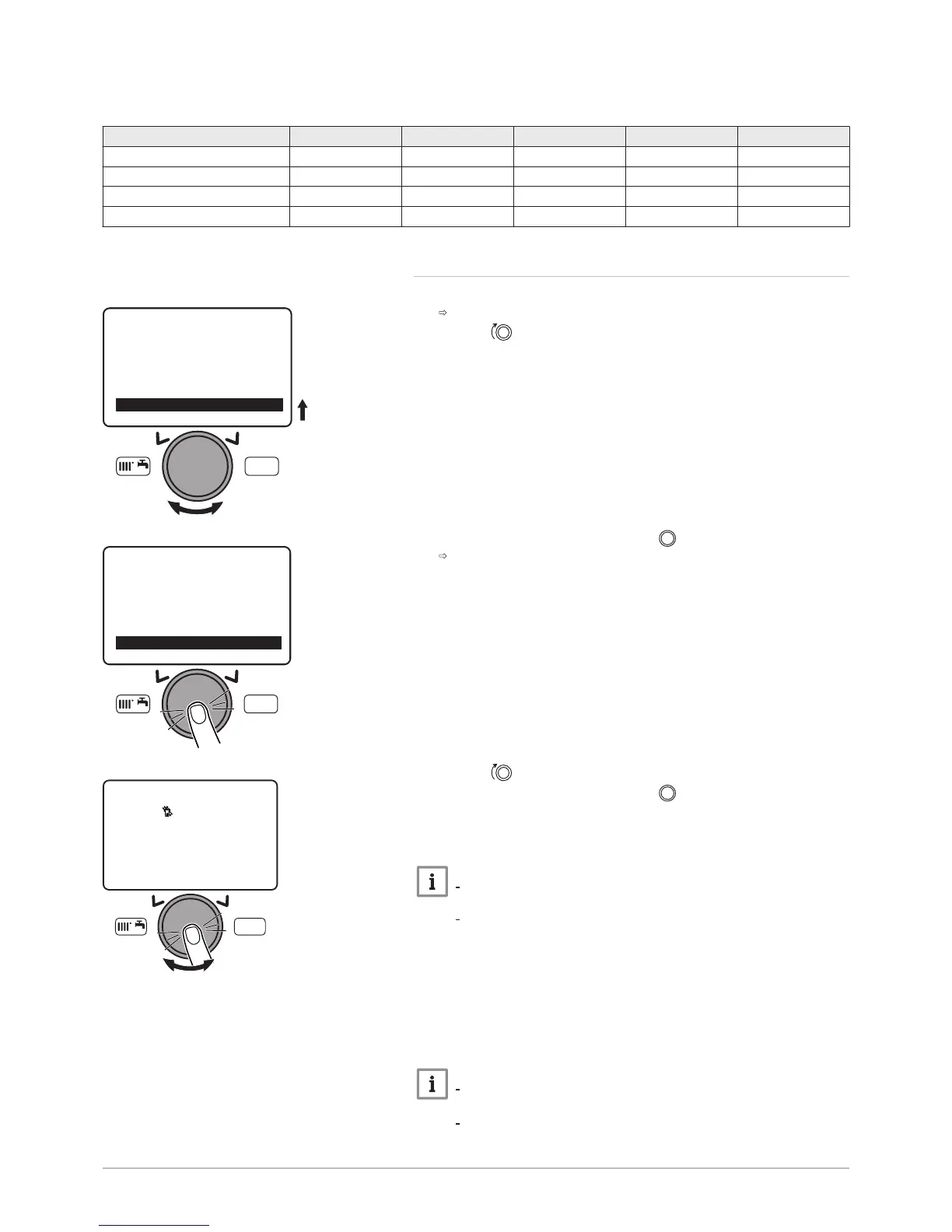
1. Accessing the Chimney sweep function 303 function.
The Chimney sweep function parameter appears.
2. Turn the button to select Chimney sweep function.
3. Confirm the selection by pressing the button.
The 303 function appears.
4. Turn the button to select Partial load.
5. Confirm the selection by pressing the button.
6. Unscrew the left-hand plug, which corresponds to the flue gas
measurement point connection.
7. Connect the flue gas analyser to the connection on the left.
Important
Ensure that the opening around the sensor is completely sealed
when taking measurements.
POWER HT+ 1.130 and POWER HT+ 1.150: Insert the sensor
into the flue gas measurement point to at least 8 cm.
8. Set the boiler's heat input to 0%.
9. Measure the percentage of CO
2
in the flue gases.
10. Compare the values measured with the authorised CO
2
range in the
Control and setting values table.
11. If necessary, adjust the air/gas ratio using the OFFSET adjustment
screw.
Important
Turn the gas adjustment screw clockwise to increase the CO
2
content.
Turn the gas adjustment screw counter-clockwise to reduce the
CO
2
content.
Fig.93
 Loading...


