5. Fit the circulating pump on the heating return pipe (circulating pump
not provided).
7.3.2 Connecting the expansion vessel
1. Determine the volume of the expansion vessel according to the
volume of water in the heating circuit.
2. Connect the expansion vessel to the heating circuit return pipe.
Volume of the expansion vessel on the heating circuit
Tab.16 Volume of the expansion vessel in relation with the volume of heating circuit
Initial pressure of
the expansion ves
sel
Volume of the installation (in litres)
100 125 150 175 200 250 300 > 300
50 kPa
(0.5 bar)
4.8 6.0 7.2 8.4 9.6 12.0 14.4 Volume of the installation x
0.048
100 kPa
(1 bar)
8.0 10.0 12.0 14.0 16.0 20.0 24.0 Volume of the installation x
0.080
150 kPa
(1.5 bar)
13.3 16.6 20.0 23.3 26.6 33.3 39.9 Volume of the installation x
0.133
Terms and conditions of validity:
Safety valve calibrated to 0.6 MPa (6 bar).
Average water temperature: 70°C.
Heating circuit flow temperature: 80°C.
Heating circuit return temperature: 60°C.
Filling pressure in the system lower than or equal to the initial pressure
in the expansion vessel.
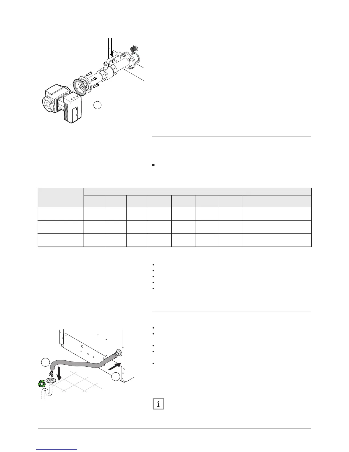
7.3.3 Connecting the condensate discharge pipe
The condensate discharge pipe is located inside the boiler.
Do not block the condensate discharge pipe.
Set the discharge pipe at a gradient of at least 30 mm per metre,
maximum horizontal length 5 metres.
Do not drain condensation water into a roof gutter.
Connect the condensate discharge pipe in accordance with prevailing
standards.
It is preferable to use the condensate neutralisers recommended by the
manufacturer of the boiler.
1. Connect a plastic hose to the condensate discharge outlet (DN18) or
a rigid pipe (DN32).
2. Insert the other end of the hose into a waste water discharge outlet.
Important
Treat the condensate in accordance with prevailing local
regulations.
Fig.68
 Loading...


