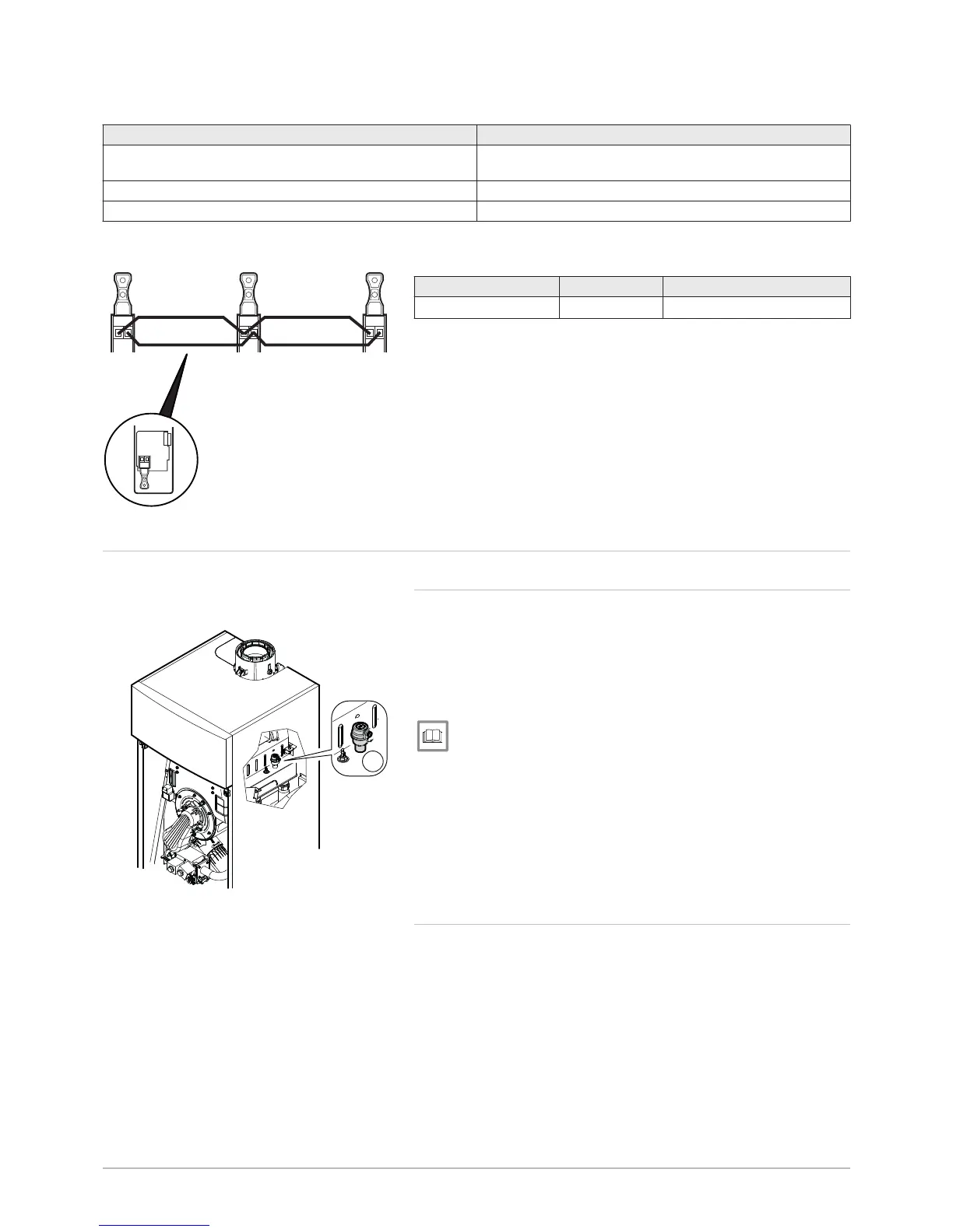
Tab.25 Connecting the boiler components in cascade
Component 1 Component 2
OCI 345 module on the boiler X30 connector on the boiler PCB. (Flat cable supplied with the
OCI 345 module)
MB connector of a OCI 345 module MB connector of a boiler OCI 345 module
DB connector of a OCI 345 module DB connector of a boiler OCI 345 module
To make the connections between the various MB and DB connectors,
use a shielded cable with the following specifications:
Type Cross section Maximum length
HAR H05 VV-F
2 x 1.5 mm
2
200 m
7.7 Filling the installation
7.7.1 POWER HT+ 1.130 and POWER HT+ 1.150
Before filling the heating installation, rinse it thoroughly.
1. Open the plug on the automatic air vent.
2. Fill the heating system until you reach a pressure of between 0.15 and
0.2 MPa (1.5 and 2 bar).
3. Check the tightness of the hydraulic connections.
4. Completely vent the heating circuit for optimum running.
For more information, see
Flushing new installations and installations less than 6 months old,
page 64
Flushing an existing installation, page 64
7.7.2 POWER HT+ 1.200 and POWER HT+ 1.250
Before filling the heating installation, rinse it thoroughly.
Fig.85 Connecting OCI 345 modules for
boilers in cascade
 Loading...


