II-10
2.2 OUTLINE OF CONTROL ELECTRONICS
2.2.1 Configuration of the Electronic Part
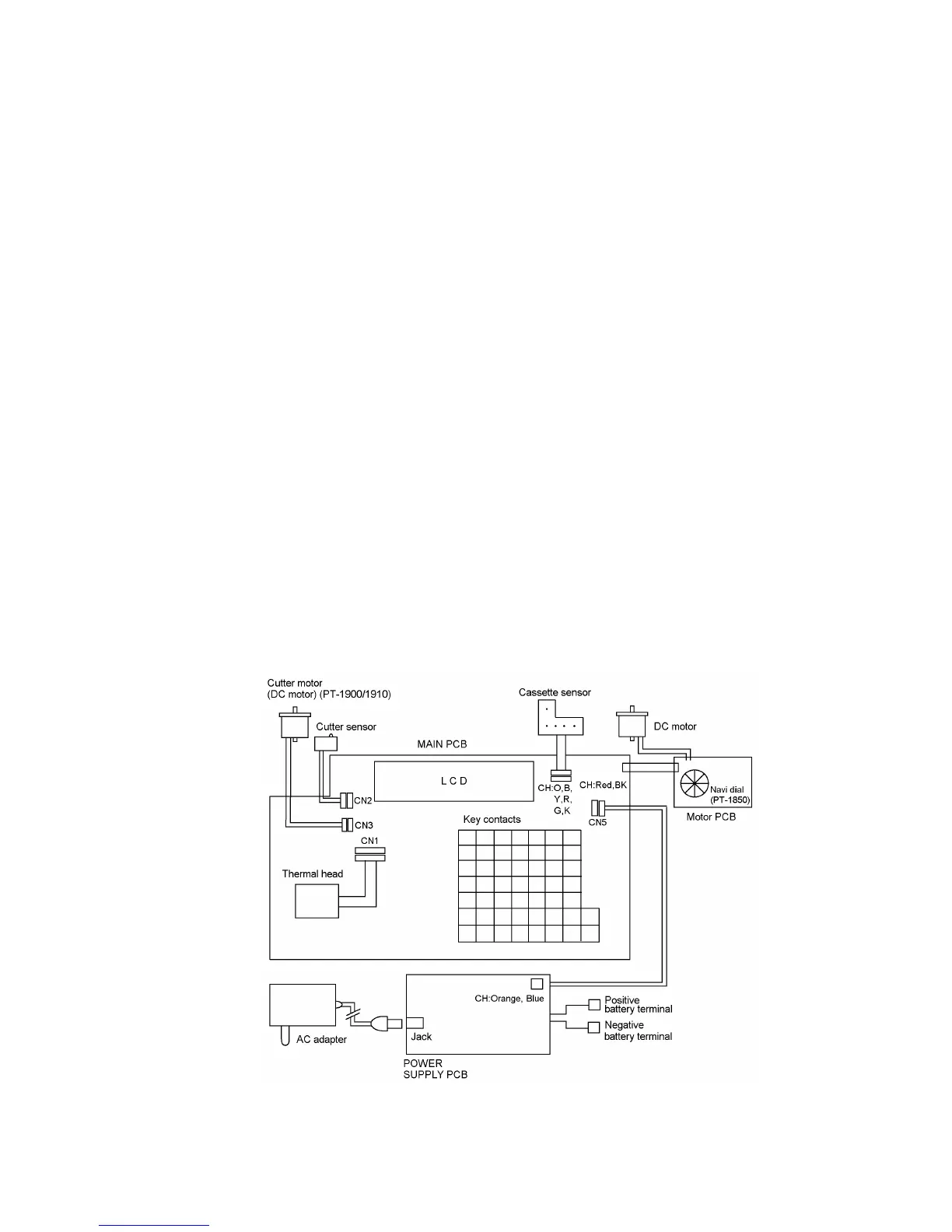
Fig. 2.2-1 shows a block diagram of the control electronics of the PT-1900/1910/1850. The control
electronics consists of three printed circuit boards (main PCB, motor PCB, and power supply
PCB), a tape feed motor, a cutter motor (PT-1900/1910), and a thermal print head assembly.
2.2.2 Main PCB
This manages all the PT-1900/1910/1850 components including an LCD, key pad, two DC motors
(PT-1850: One DC motor), and thermal print head.
Note: When mounting the chips onto the PCB, use the lead-free solder.
2.2.3 Power Supply PCB
This has electrolytic capacitors (as filters for output lines), an AC adapter jack, battery terminal
plates, and other related electronic devices to feed power to the control electronics and the DC
motors from the AC adapter or batteries.
Note: When mounting the chips onto the PCB, use the lead-free solder.
2.2.4 Cassette Sensor
This supports the sensors that detect the tape width and ink ribbon type in the tape cassette.
2.2.5 DC Motors
This machine has two DC motors (PT-1850: One DC motor). One feeds tape and ink ribbon and
the other drives the cutter to cut (PT-1900/1910) the tape.
2.2.6 Thermal Print Head
This is a thick-film thermal print head which integrates a heat generator (consisting of 128 heating
elements vertically aligned) and driver circuitry.
Fig. 2.2-1 Control Electronics of PT-1900/1910/1850
 Loading...