III-16
[ 5 ] Removing the Main PCB Unit and Rubber Key Pad
When you handle the PCB, it is recommended that an anti-static mat be used. If you have built up
a static charge, touching the PCB without any anti-static control may damage the LSI and other
electronic devices.
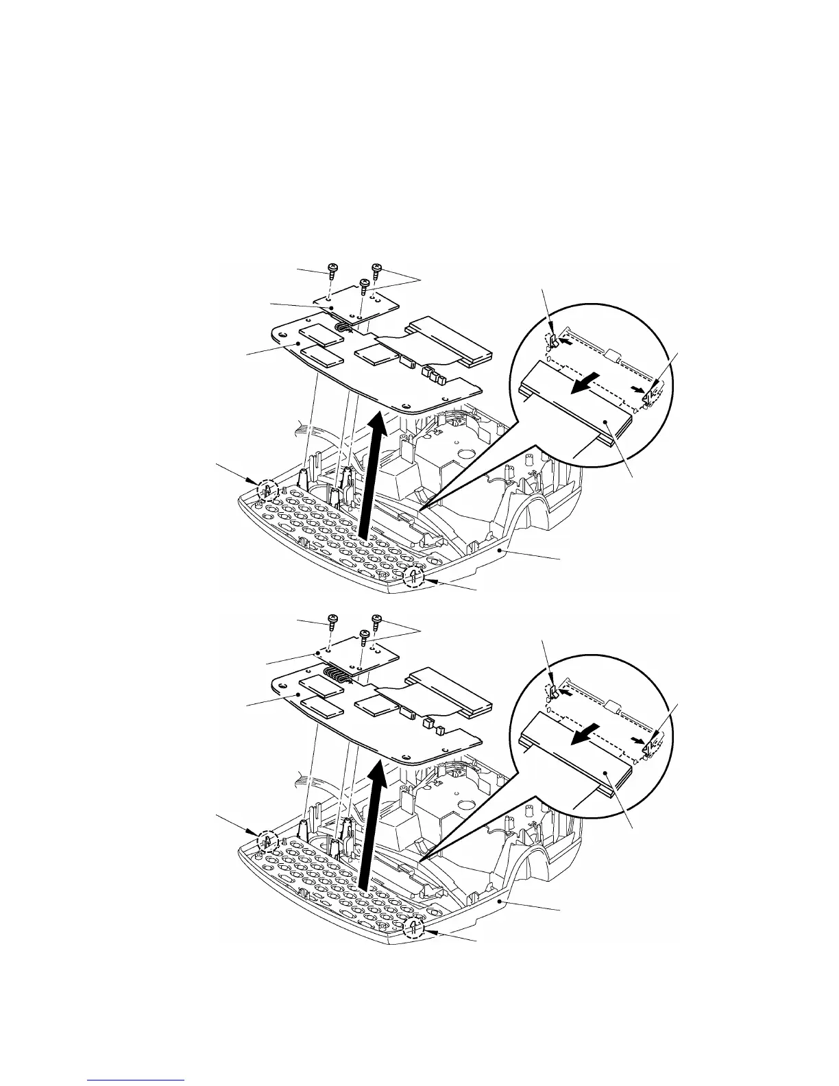
(1) Remove three screws to remove the DC motor PCB from the upper cover.
(2) Unhook the two latches to release the main PCB unit.
(3) Pull the positions “A” outwards to pull the LCD with the main PCB unit in the direction of the
arrow shown in the figure below and remove the main PCB unit.
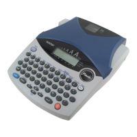
(PT-1900/1910)
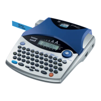
(PT-1850)
Fig. 3.1-16 Removing the Main PCB Unit and DC Motor PCB (1)
“A”
Screw
DC motor PCB
(Main PCB)
Screws
Main PCB unit
Latch
LCD
Latch
Upper cover
“A”
Screw
DC motor PCB
(Main PCB)
Latch
Latch
Upper cover
LCD
Main PCB unit
“A”
“A”
Screws
 Loading...