ON
ON
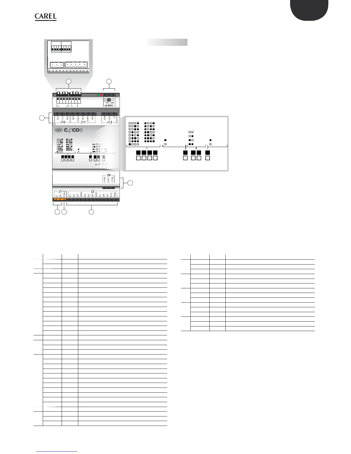
Factory setting:
address = not configured
extension = no offset
Baud Rate = 19.2 K
protocol = Modbus
Basic version
Address Ext Baud Prot
15 10
1 2 3
6
8
ENG
c.pCO sistema +0300057EN rel. 1.2 - 29.05.2017
Fig. 4.t
Description of connection terminals on c.pCO mini/c.pCOe
See the gures on the previous pages relating to c.pCO mini/c.pCOe
Ref. Term. Label Description
1
J1-1 G Power supply at voltage A(*)
J1-2 G0 Power supply reference
2 J1-3 Vbat Power supply from external Ultracap module
3
J2-1 U1 Universal input/output 1
J2-2 U2 Universal input/output 2
J2-3 U3 Universal input/output 3
J2-4 GND Common for universal inputs/outputs 1, 2, 3
J2-5 U4 Universal input/output 4
J2-6 U5 Universal input/output 5
J2-7 U6 Universal input/output 6
J2-8 GND Common for universal inputs/outputs 4, 5, 6
J2-9 U7 Universal input/output 7
J2-10 U8 Universal input/output 8
J2-11 U9 Universal input/output 9
J2-12 U10 Universal input/output 10
J2-13 GND Common for universal inputs/outputs 7, 8, 9, 10
4 J3-1 +Vterm Power supply for additional terminal
5
J3-2 Tx-/Rx- Terminal RS485 port Tx-/Rx-
J3-3 Tx+/Rx+ Terminal RS485 port Tx+/Rx+
J3-4 GND Terminal RS485 port GND
6
J10-1 NO1 Normally open contact, relay 1
J10-2 C1/2 Common for relay 1, 2
J10-3 NO2 Normally open contact, relay 2
J11-1 NO3 Normally open contact, relay 3
J11-2 C3/4/5 Common for relay 3, 4, 5
J11-3 NO4 Normally open contact, relay 4
J11-4 C3/4/5 Common for relay 3, 4, 5
J11-5 NO5 Normally open contact, relay 5
J12-1 NO6 Normally open contact, relay 6
J12-2 NC6 Normally closed contact, relay 6
J12-3 C6 Common for relay 6
7 J7 - Single-pole valve connector
8
J9-1 +5 V
REF Power supply ratiometric probes 0 to 5 V
J9-2 GND Power supply common
J9-3 +VDC Power to active probes
Ref. Term. Label Description
9
J4-1 Tx-/Rx- FieldBus RS485 port Tx-/Rx-
J4-2 Tx+/Rx+ FieldBus RS485 port Tx+/Rx+
J4-3 GND FieldBus RS485 port GND
10
J6-1 Tx-/Rx- BMS RS485 port Tx-/Rx-
J6-2 Tx+/Rx+ BMS RS485 port Tx+/Rx+
J6-3 GND BMS RS485 port GND
11
J8-4 Y1 Analogue output 1, 0...10 V
J8-5 Y2 Analogue output 2, 0...10 V
J8-6 GND Common for analogue outputs 1, 2
12
J8-1 ID1 Digital input 1
J8-2 ID2 Digital input 2
J8-3 GND Common for digital inputs 1, 2
13
J5-1 TxL/RxL CANbus port TxL/RxL
J5-2 TxH/RxH CANbus port TxH/RxH
J5-3 GND CANbus port GND
(*) Voltage A: 24 Vac o 28...36 Vdc
c.pCOe - DIN rail version
 Loading...


