Check SiBE12-908
177 Service Diagnosis
3.12 Rotating Pulse Input on Outdoor Unit PCB Check
Check No.23 < For outdoor fan motor or humidifying fan motor>
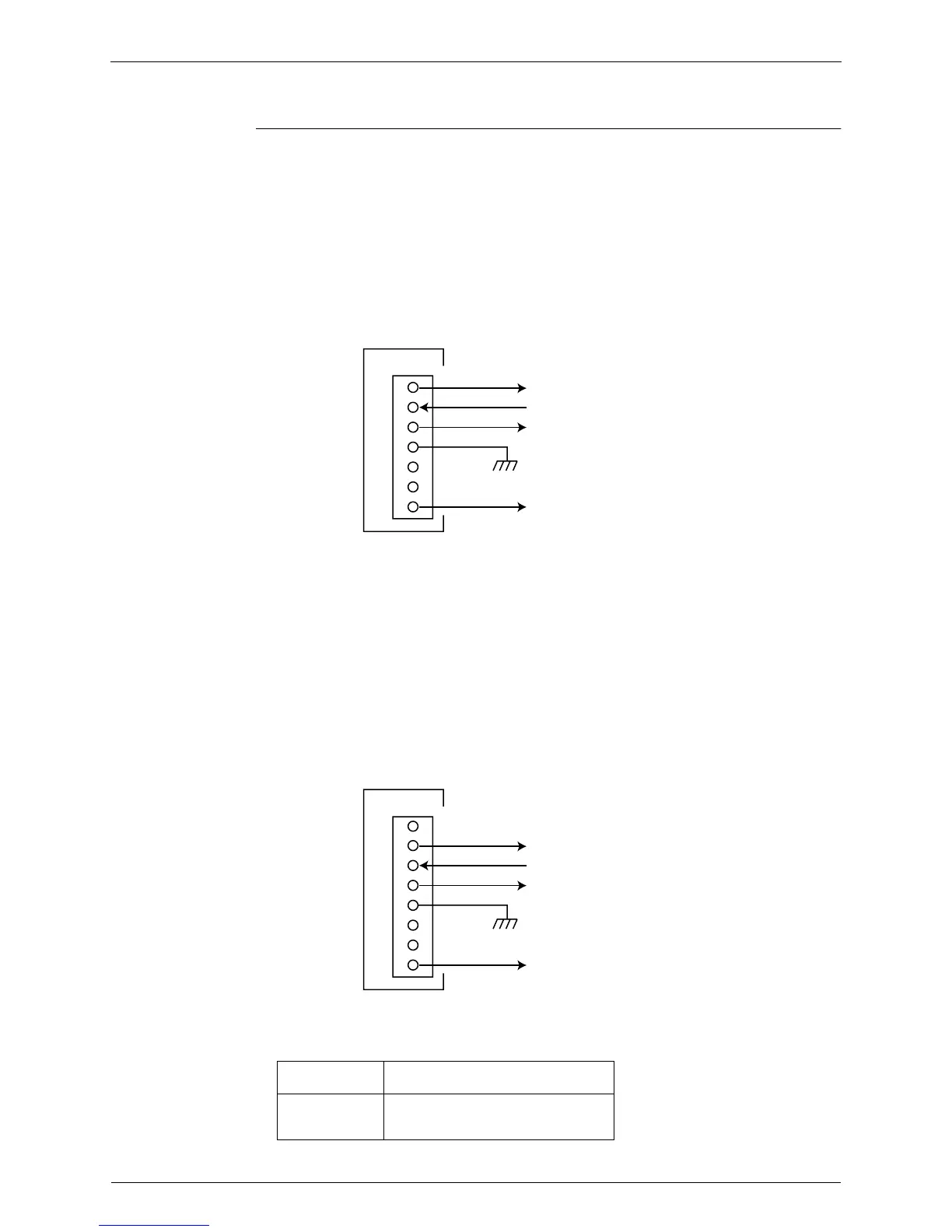
Outdoor fan motor
Make sure that the voltage of 270 ± 30 V is applied.
1. Set operation OFF and power OFF. Remove the connector S70.
2. Check that the voltage between the pins 4-7 is 270 VDC.
3. Check that the control voltage between the pins 3-4 is 15 VDC.
4. Check that the rotation command voltage between the pins 2-4 is 5 VDC.
5. Keep operation OFF and power OFF. Connect the connector S70.
6. Check whether 2 pulses (0 - 15 V) are output at the pins 1-4 when the fan motor is rotated 1
turn by hand.
Humidifying fan motor
Make sure that the voltage of 270 ± 30 V is applied.
1. Set operation OFF and power OFF. Remove the connector S72.
2. Check that the voltage between the pins 5-8 is 270 VDC.
3. Check that the control voltage between the pins 4-5 is 15 VDC.
4. Check that the rotation command voltage between the pins 3-5 is 5 VDC.
5. Keep operation OFF and power OFF. Connect the connector S72.
6. Check whether 2 pulses (0 - 15 V) are output at the pins 2-5 when the fan motor is rotated 1
turn by hand.
Fuses are commonly used as follows. Refer to the corresponding wiring diagram.
When the FU2 is melted, check the outdoor fan motor for proper function.
FU1
SW power supply
Hygroscopic fan motor
FU2
Outdoor fan motor
Humidifying fan motor
Four way valve
(R10759)
PCB
S70
1
2
3
4
5
6
7
Actual rotating pulse output (0-15V)
Rotation command pulse input (0-15V)
15V
DC270V
(R10760)
PCB
S70
1
2
3
4
5
6
7
8
Actual rotating pulse output (0-15V)
Rotation command pulse input (0-15V)
15V
DC270V
 Loading...