SiBE12-908 Operation Manual
Installation / Operation Manual 80
3. Operation Manual
3.1 Names of Parts
Name of Parts
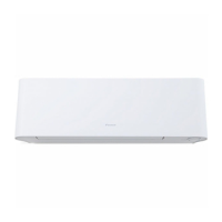
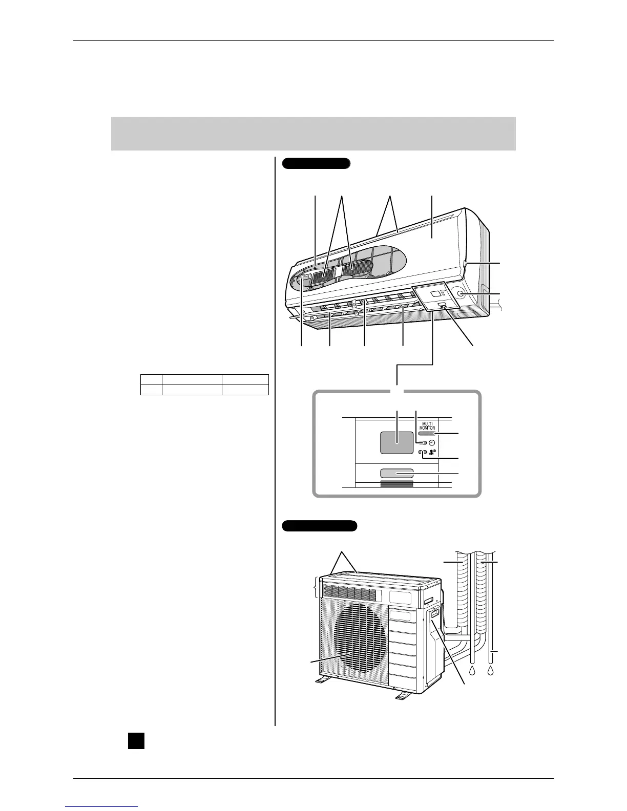
Indoor Unit
1.Air filter
2.Titanium apatite photocatalytic
air-purifying filter:
• These filters are attached to the inside of the air
filters.
3.Air inlet
4.Front panel
5.Panel tab
6.Room temperature and humidity
sensors:
• It senses the air temperature and humidity around
the unit.
7.INTELLIGENT EYE sensor: (page 15.)
8.Control panel
9.Air outlet
10.Flaps (horizontal blades): (page 10.)
11.Louvers (vertical blades):
• The louvers are inside of the air outlet. (page 10.)
12.Air supply filter (gray)
13.Indoor Unit ON/OFF switch: (page 8.)
• Push this switch once to start operation.
Push once again to stop it.
• The operation mode refers to the following table.
• This switch is useful when the remote controller is
missing.
14.Multi-monitor lamp: (page 8.)
• The lamp color changes according to the
operation.
• AUTO.............................................Blue/Red
• DRY ...............................................Green
• COOL.............................................Blue
• HEAT .............................................Red
• FAN................................................White
15.TIMER lamp (yellow): (page 19.)
16.INTELLIGENT EYE lamp (green): (page 15.)
17.Signal receiver:
• It receives signals from the remote controller.
• When the unit receives a signal, you will hear a
short beep.
• Operation start...............................beep-beep
• Settings changed.........................beep
• Operation stop.............................beeeeep
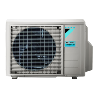
Outdoor Unit
18.Air inlet: (Back and side)
19.Refrigerant piping, humidifying hose and
inter-unit cables
20.Drain hoses
21.Earth terminals:
• It is inside of this cover.
22.Air outlet
23.Humidifying hoses
24.Humidity unit
17 15
16
13
1923
20
21
134
5
7
91110
8
2
18
24
22
612
14
Indoor Unit
Outdoor Unit
Mode Temperature setting Airflow rate
AUTO 25°C AUTO
4
 Loading...