•
•
•
•
•
•
•
•
•
•
•
•
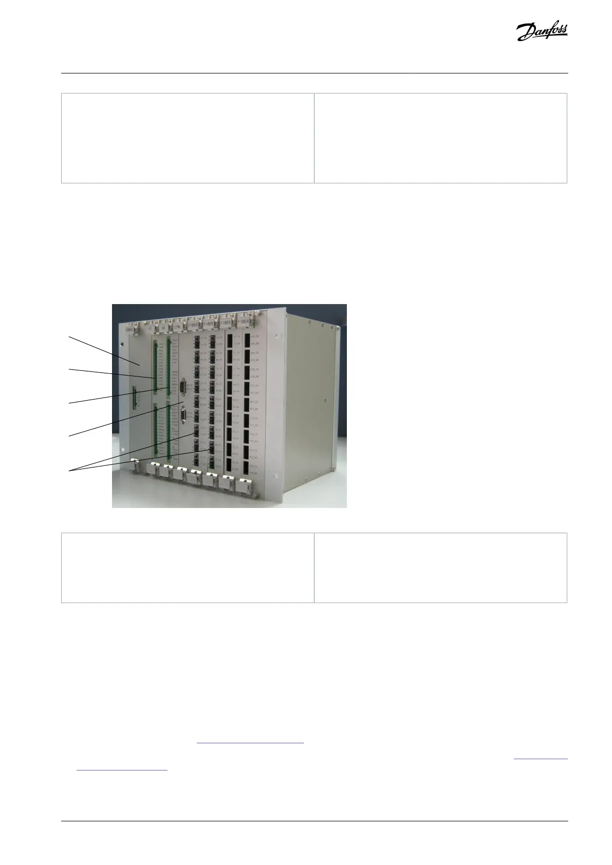
The main control system is mounted in the control rack and consists of:
Main control board
I/O board
A/D board
Two fiber optical boards (extendable)
Power supply board
Bus motherboard, which connects the boards to each other.
Illustration 5: Main Control System
3.3.1.1 Controls and Indicators
The following are mounted on the control cabinet door:
High voltage power-on indicator: A green indicator, which indicates high voltage applied to the drive.
Operation indicator: A green indicator, which indicates that the drive is in operation.
Fault indicator: A red indicator, which indicates that the system is in “failure” state.
Emergency Stop button (E-stop): This button is used to break the high-voltage power of the drive when the system has an
emergency (such as unexpected incidents threatening the safety of the personnel or equipment). The button has a self-locking
function. Turn the button clockwise to reset and to turn power on again.
Human-machine interface: See 7 Human-Machine Interface.
Mechanical interlocking system: Standard in UL type drives and available as option +MMKI for IEC type drives. See 8.6.2 Mechan-
ical Interlocking System.
AQ363633621020en-000201 / 172F3117 | 17Danfoss A/S © 2021.06
Product Overview
VACON® 1000
Operating Guide

 Loading...


