•
•
•
Number of power cells per phase
3.4.2 Power Cells
The power cell is the basic module of the medium-voltage drive, which produces a variable voltage and frequency output. It is com-
posed of fast acting fuses, a rectification bridge, DC-link capacitance, IGBT inverting bridge, and so on.
The input terminals of the power cells are connected with the 3-phase winding of the secondary side of the phase-shift transformer.
The 3-phase diode provides full-wave rectification to charge the DC-link capacitance, and the voltage on the capacitance is provi-
ded to the H-bridge 1-phase bridge inverter circuit formed by 4 IGBTs.
The power cell receives signals through optical fibers, and controls the closing and opening of the S1–S4 IGBTs by using PWM mod-
ulation mode to output a 1-phase impulse modulated waveform. Each cell has only 3 possible output states:
When S1 and S4 are closed, the state of the output voltage V
UV
is V
DC
.
When S2 and S3 are closed, the output voltage V
UV
is -V
DC
.
When S1 and S3 or S2 and S4 are closed, the output voltage V
UV
is 0.
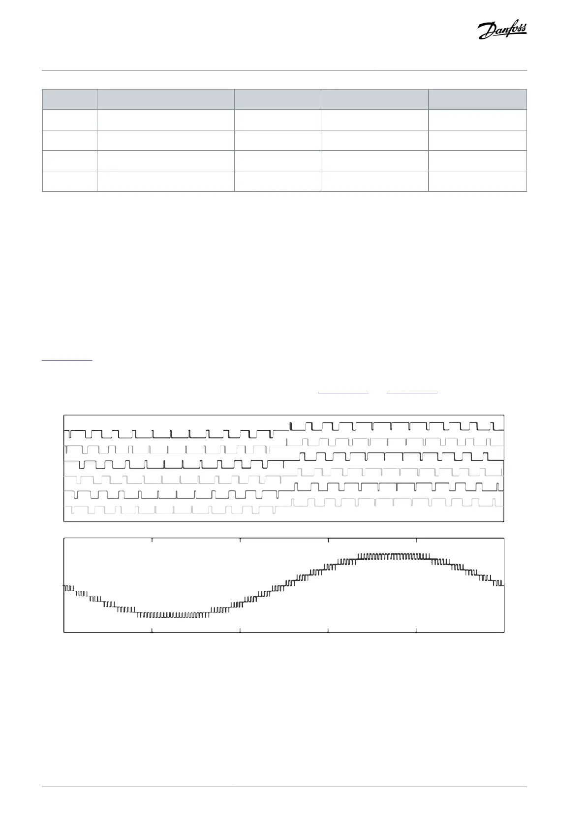
Illustration 25 shows the waveform diagram of the output voltage of each power cell and the superimposed output phase voltage
waveform when 6 cells are connected in series. As shown in the figure, 13 voltage levels are obtained through connecting the 6
power cells in series. The increasing number of the voltage levels reduces the distortion content of the output voltage and simulta-
neously lowers the risk of damaging the motor insulation caused by dU/dt. Illustration 26 and Illustration 27 are the waveform dia-
grams of the output voltage and current of the drive when loaded by a motor.
PWM6
Time (ms)
Output phase voltage
0 4 8 12 16
20
e30bi655.10
Illustration 25: Output and Phase-Voltage Diagrams
AQ363633621020en-000201 / 172F311730 | Danfoss A/S © 2021.06
Product Overview
VACON® 1000
Operating Guide

 Loading...


