Communication fail indicator
Overtemperature indicator
50 V DC-link voltage indicator
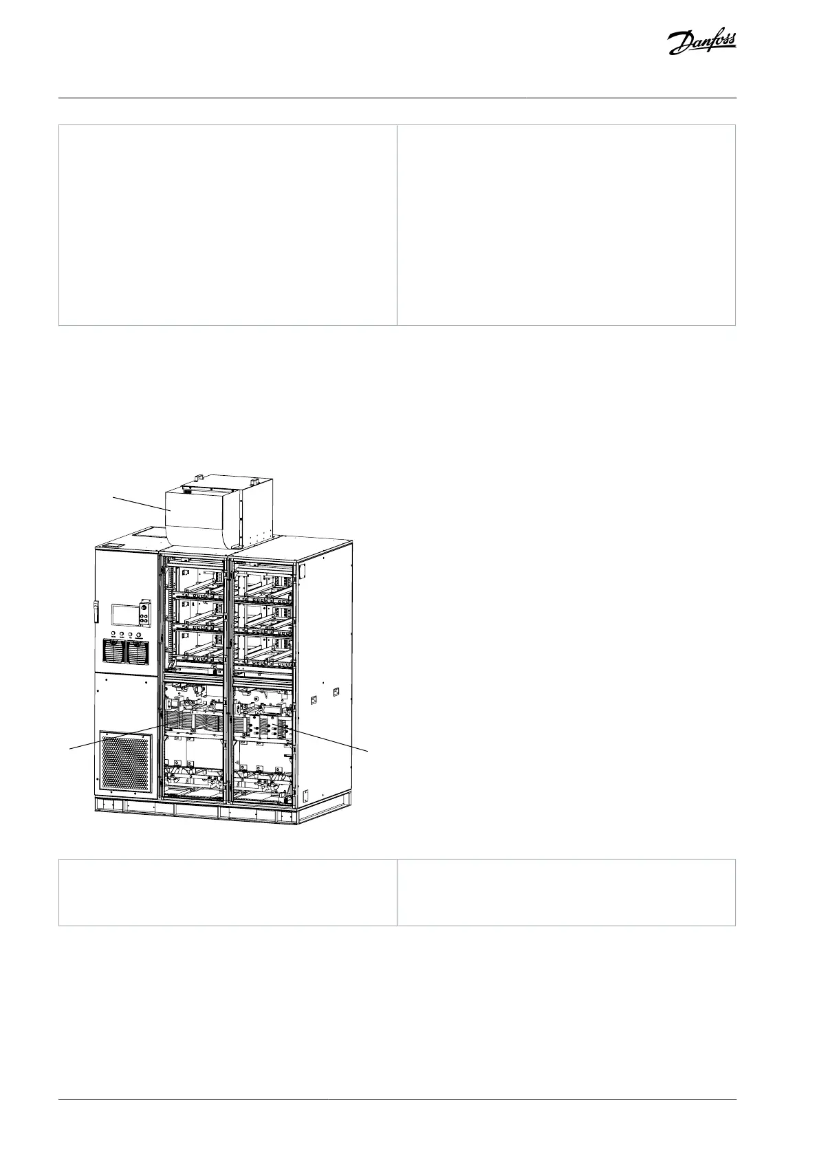
3.3.3 Transformer Cabinet
The transformer cabinet includes the phase-shift transformer and its accessories.
The transformer is integrated with the cabinet base through screws for the convenience of transportation and installation. The sys-
tem default setting is that, when the transformer temperature exceeds 95°C, the system reports an excessive high temperature
alarm but does not shut down. When the temperature exceeds 110°C, the system reports an extra-high temperature fault and shuts
down.
In standalone systems, the same fan is used to cool the transformer and power cell cabinets.
Illustration 10: Transformer Cabinet in VACON® 1000 Standalone Systems
Input current Hall sensor
AQ363633621020en-000201 / 172F311720 | Danfoss A/S © 2021.06
Product Overview
VACON® 1000
Operating Guide

 Loading...


