Input) to [32] Pulse input. If terminal 29 is used as an input,
set parameter 5-01 Terminal 27 Mode to [0] Input.
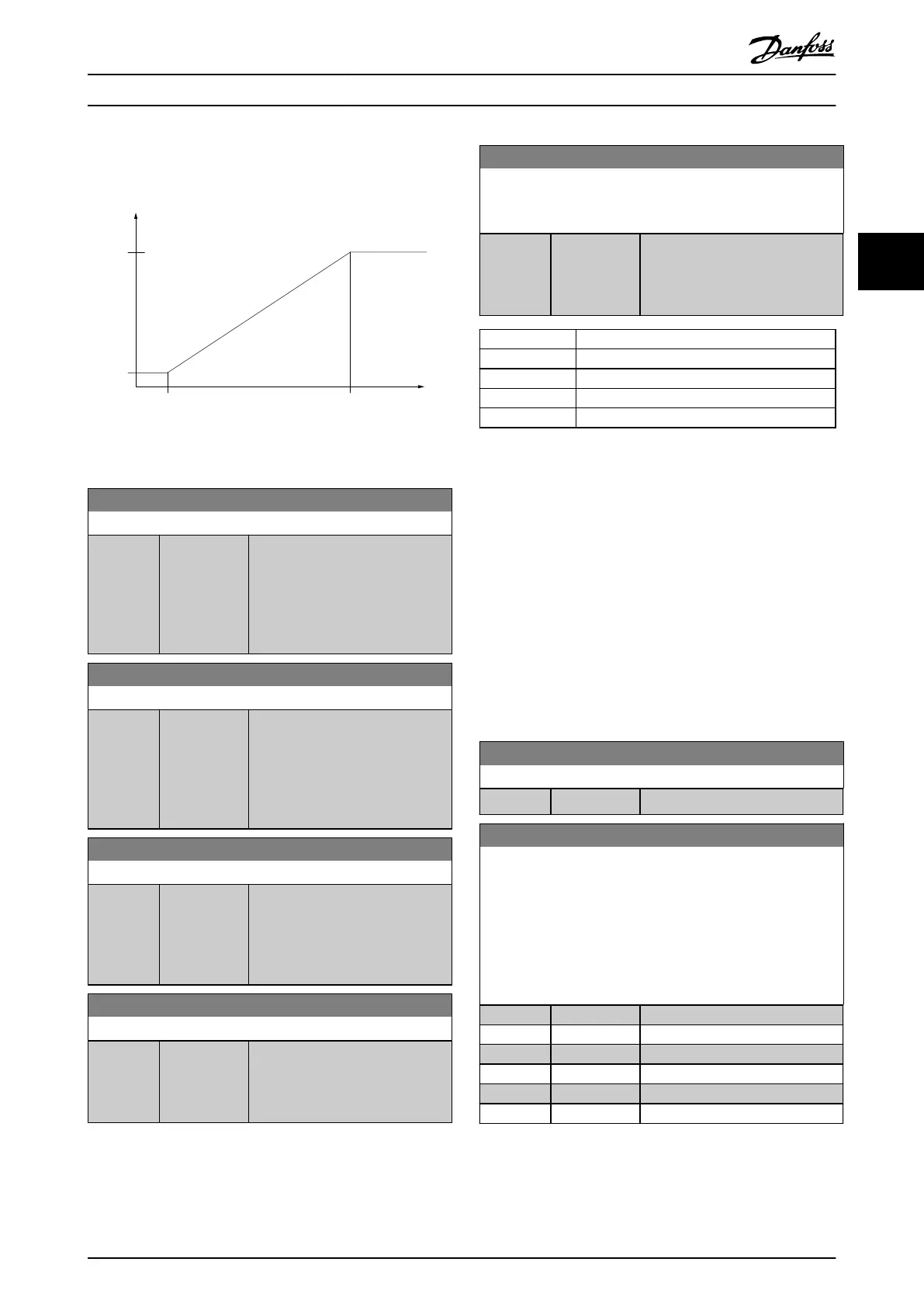
130BA076.10
(RPM)
Ref.
Low freq.
P 5-50/
P 5-55
Input
(Hz)
High
ref.
value
P 5-53/
p 5-58
High freq.
P 5-51/
P 5-56
Low
ref.
value
P 5-52/
p 5-57
Illustration 3.7 Pulse Input
5-50 Term. 29 Low Frequency
Range: Function:
20 Hz* [20 - 31999
Hz]
Enter the low frequency limit
corresponding to the low
compressor shaft speed (that is, low
reference value) in
parameter 5-52 Term. 29 Low Ref./
Feedb. Value. See Illustration 3.7.
5-51 Term. 29 High Frequency
Range: Function:
32000 Hz* [21 - 32000
Hz]
Enter the high frequency limit
corresponding to the high
compressor shaft speed (that is,
high reference value) in
parameter 5-53 Term. 29 High Ref./
Feedb. Value.
5-52 Term. 29 Low Ref./Feedb. Value
Range: Function:
0* [-4999 -
4999 ]
Enter the low reference value limit
for the compressor shaft speed
[RPM]. This is also the lowest
feedback value. Set terminal 29 to
digital input.
5-53 Term. 29 High Ref./Feedb. Value
Range: Function:
Size
related*
[-4999 -
4999 ]
Enter the high reference value
[RPM] for the compressor shaft
speed and the high feedback value.
Select terminal 29 as a digital input.
3.6.5 5-9* Bus Controlled
This parameter group selects digital and relay outputs via a
eldbus setting.
5-90 Digital & Relay Bus Control
This parameter holds the state of the buscontrolled digital
outputs and relays.
Range: Function:
0* [0 -
0xFFFFFFFF ]
A logical 1 indicates that the
output is high or active. A logical 0
indicates that the output is low or
inactive.
Bit 0-3 Reserved
Bit 4 Relay 1 output terminal
Bit 6-23 Reserved
Bit 24 Terminal 42 digital output
Bit 26-31 Reserved
Table 3.4 Bit Functions
3.7 Main Menu - Analog In/Out - Group 6
Parameter group for setting up the analog I/O congu-
ration and the digital output.
The frequency converter provides 2 analog inputs:
•
Terminal 53.
•
Terminal 54.
The analog inputs can be freely allocated to either voltage
(0–10 V) or current input (0/4–20 mA).
3.7.1 6-0* Analog I/O Mode
6-00 Live Zero Timeout Time
Range: Function:
10 s* [1 - 99 s] Enter the timeout time.
6-01 Live Zero Timeout Function
Select the timeout function. The function set in
parameter 6-01 Live Zero Timeout Function is activated if the input
signal on terminal 53 or 54 is below 50% of the value in
parameter 6-10 Terminal 53 Low Voltage, parameter 6-12 Terminal
53 Low Current, parameter 6-20 Terminal 54 Low Voltage, or
parameter 6-22 Terminal 54 Low Current for a time period dened
in parameter 6-00 Live Zero Timeout Time.
Option: Function:
[0] * O
[1] Freeze output
[2] Stop
[3] Jogging
[4] Max. speed
[5] Stop and trip
Parameters Programming Guide
MG18P202 Danfoss A/S © 06/2019 All rights reserved. 35
3 3
 Loading...


