4 Troubleshooting
4.1 Alarms and Warnings
A warning or an alarm is signaled by the relevant LED on
the front of the frequency converter and indicated by a
code on the display.
A warning remains active until its cause is no longer
present. Under certain circumstances, operation of the
compressor may still be continued. Warning messages may
be critical.
In the event of an alarm, the frequency converter has
tripped. To restart operation, reset alarms once their cause
has been
rectied.
This may be done in 4 ways:
•
By pressing [Reset].
•
Via a digital input with the Reset function.
•
Via serial communication.
•
By resetting automatically using the [Auto Reset]
function, see parameter 14-20 Reset Mode.
NOTICE
After a manual reset pressing [Reset], press [Auto On] or
[Hand On] to restart the compressor.
If an alarm cannot be reset, the reason may be that its
cause has not been rectied, or the alarm is trip-locked,
see Table 4.1.
CAUTION
Alarms that are trip-locked oer extra protection,
meaning that the mains supply must be switched o
before the alarm can be reset. After being switched back
on, the frequency converter is no longer blocked and
may be reset as described above once the cause has
been rectied.
Alarms that are not trip-locked can also be reset using
the automatic reset function in parameter 14-20 Reset
Mode (Warning: automatic wake-up is possible!)
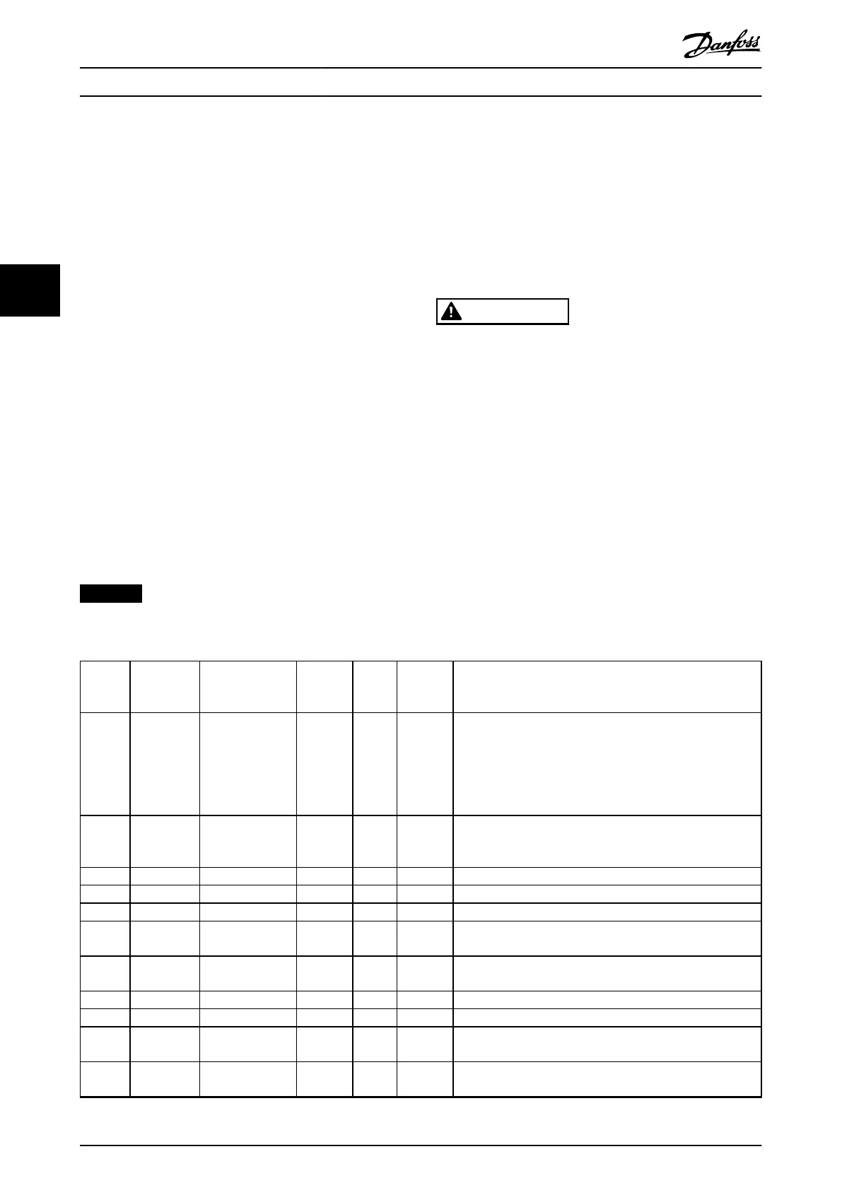
Table 4.1 species whether a warning occurs before an
alarm, or whether to show a warning or an alarm for a
given fault.
This is possible, for instance, in parameter 1-90 Motor
Thermal Protection. After an alarm or trip, the compressor
carries on coasting, and the alarm and warning ash on
the frequency converter. Once the problem has been
rectied, only the alarm continues ashing.
Fault
number
Alarm/
Warning bit
number
Fault text Warning Alarm Trip
locked
Cause of problem
2 16 Live zero error X X
Signal on terminal 53 or 54 is less than 50% of the value set
in parameter 6-10 Terminal 53 Low Voltage,
parameter 6-12 Terminal 53 Low Current,
parameter 6-20 Terminal 54 Low Voltage, or
parameter 6-22 Terminal 54 Low Current. See also parameter
group 6-0* Analog I/O Mode.
4 14 Mains ph. loss X X X
Missing phase on the supply side or too high voltage
imbalance. Check the supply voltage. See
parameter 14-12 Response to Mains Imbalance.
7 11 DC over volt X X DC-link voltage exceeds limit.
8 10 DC under volt X X DC-link voltage drops below voltage warning low limit.
9 9 Inverter overload X X More than 100% load for too long.
10 8
Motor ETR
overtemperature
X X
The motor is too hot due to more than 100% load for too
long. See parameter 1-90 Motor Thermal Protection.
11 7
Motor thermistor
overtemperature
X X
The thermistor or the thermistor connection is disconnected.
See parameter 1-90 Motor Thermal Protection.
13 5 Overcurrent X X X Inverter peak current limit is exceeded.
14 2 Earth Fault X X X Discharge from output phases to ground.
16 12 Short Circuit X X
Short circuit in the compressor or on the compressor
terminals.
17 4 Ctrl. word TO X X
No communication to the frequency converter. See parameter
group 8-0* General Settings.
Troubleshooting
VLT
®
Compressor Drive CDS 803
66 Danfoss A/S © 06/2019 All rights reserved. MG18P202
44
 Loading...


