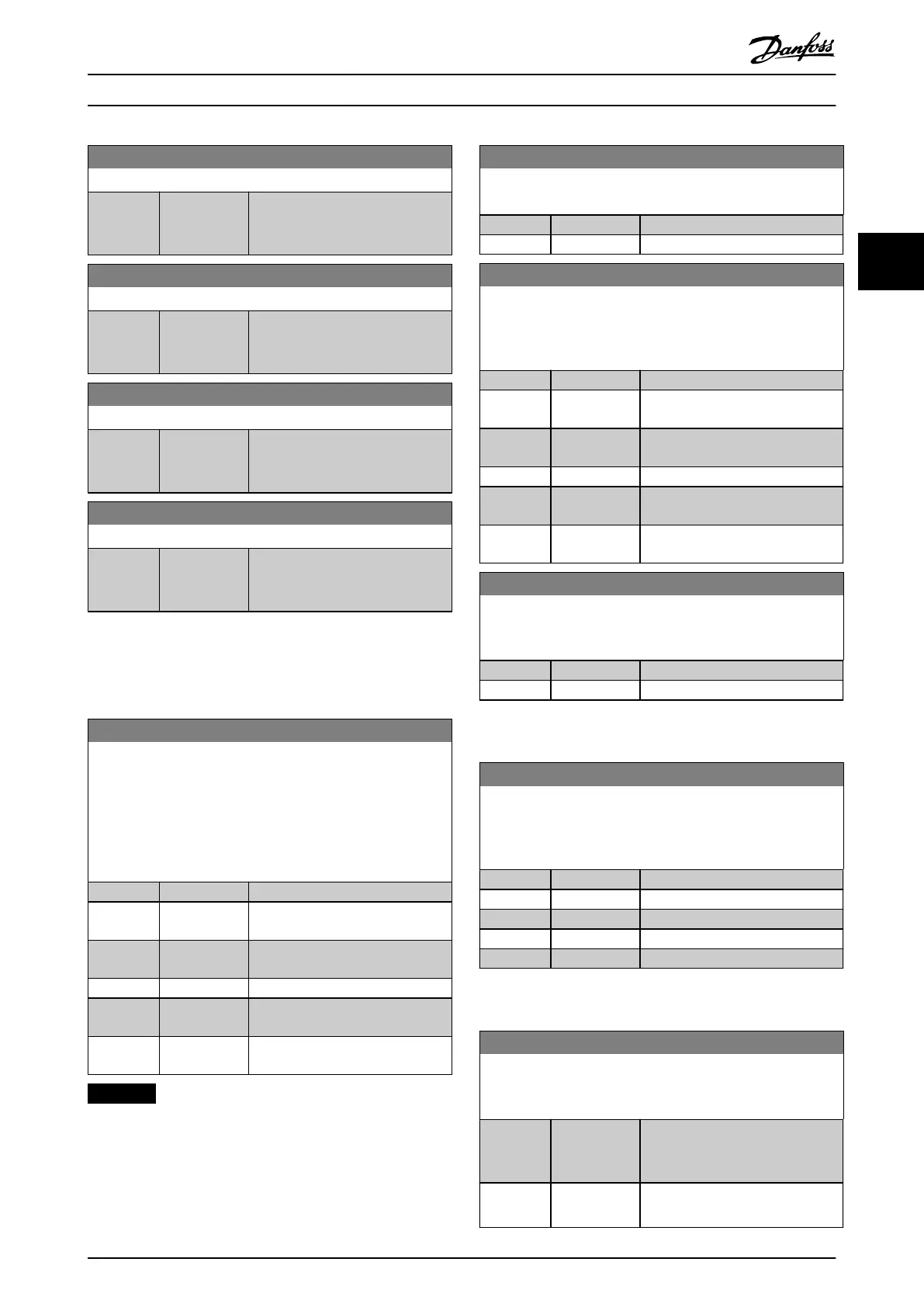
16-93 Warning Word 2
Range: Function:
0* [0 -
0xFFFFFFFFUL
]
View the warning word 2 sent via
the serial communication port in
hex code.
16-94 Ext. Status Word
Range: Function:
0* [0 -
0xFFFFFFFFUL
]
Shows the extended status word
sent via the serial communication
port in hex code.
16-95 Ext. Status Word 2
Range: Function:
0* [0 -
0xFFFFFFFFUL
]
Shows the extended status word 2
sent via the serial communication
port in hex code.
16-97 Alarm Word 3
Range: Function:
0* [0 -
0xFFFFFFFFUL
]
View the alarm word 3 sent via the
serial communication port in hex
code.
3.13 Main Menu - Drive Closed Loop -
Group 20
3.13.1 20-0* Feedback
20-00 Feedback 1 Source
Up to 3 dierent feedback signals can be used to provide the
feedback signal for the frequency converter’s PID controller.
This parameter denes which input is used as the source of the
rst feedback signal.
Analog input X30/11 and analog input X30/12 refer to inputs on
the optional General Purpose I/O board.
Option: Function:
[0] * No function
[1] Analog Input
53
[2] Analog Input
54
[3] Pulse input 29
[100] Bus Feedback
1
[101] Bus Feedback
2
NOTICE
If feedback is not used, set its source to [0] No Function.
Parameter 20-20 Feedback Function determines how the
PID controller uses the 3 possible feedbacks.
20-01 Feedback 1 Conversion
This parameter allows a conversion to be applied to feedback.
Option: Function:
[0] * Linear
[1] Square root
20-03 Feedback 2 Source
The eective feedback signal is made up of up to 3 dierent
input signals. Select which drive input should be treated as the
source of the second of these signals.
Option: Function:
[0] * No function
[1] Analog Input
53
[2] Analog Input
54
[3] Pulse input 29
[100] Bus Feedback
1
[101] Bus Feedback
2
20-04 Feedback 2 Conversion
Select a conversion for the feedback 2 signal. Select Linear to
leave the feedback signal unchanged.
Option: Function:
[0] * Linear
[1] Square root
3.13.2 20-2* Feedback/Setpoint
20-20 Feedback Function
Select how the feedback should be calculated. The feedback can
be either a single feedback source or a combination of several
feedbacks.
Option: Function:
[0] Sum
[1] Dierence
[2] Average
[3] * Minimum
[4] Maximum
3.13.3 20-8* PI Basic Settings
20-81 PI Normal/ Inverse Control
Select either [0] Normal or [1] Inverse to control the output speed
when the process error is positive.
Option: Function:
[0] * Normal Set the process control to increase
the output speed when the process
error is positive.
[1] Inverse Reduce the output speed when the
process error is positive.
Parameters Programming Guide
MG18P202 Danfoss A/S © 06/2019 All rights reserved. 63
3 3
 Loading...


