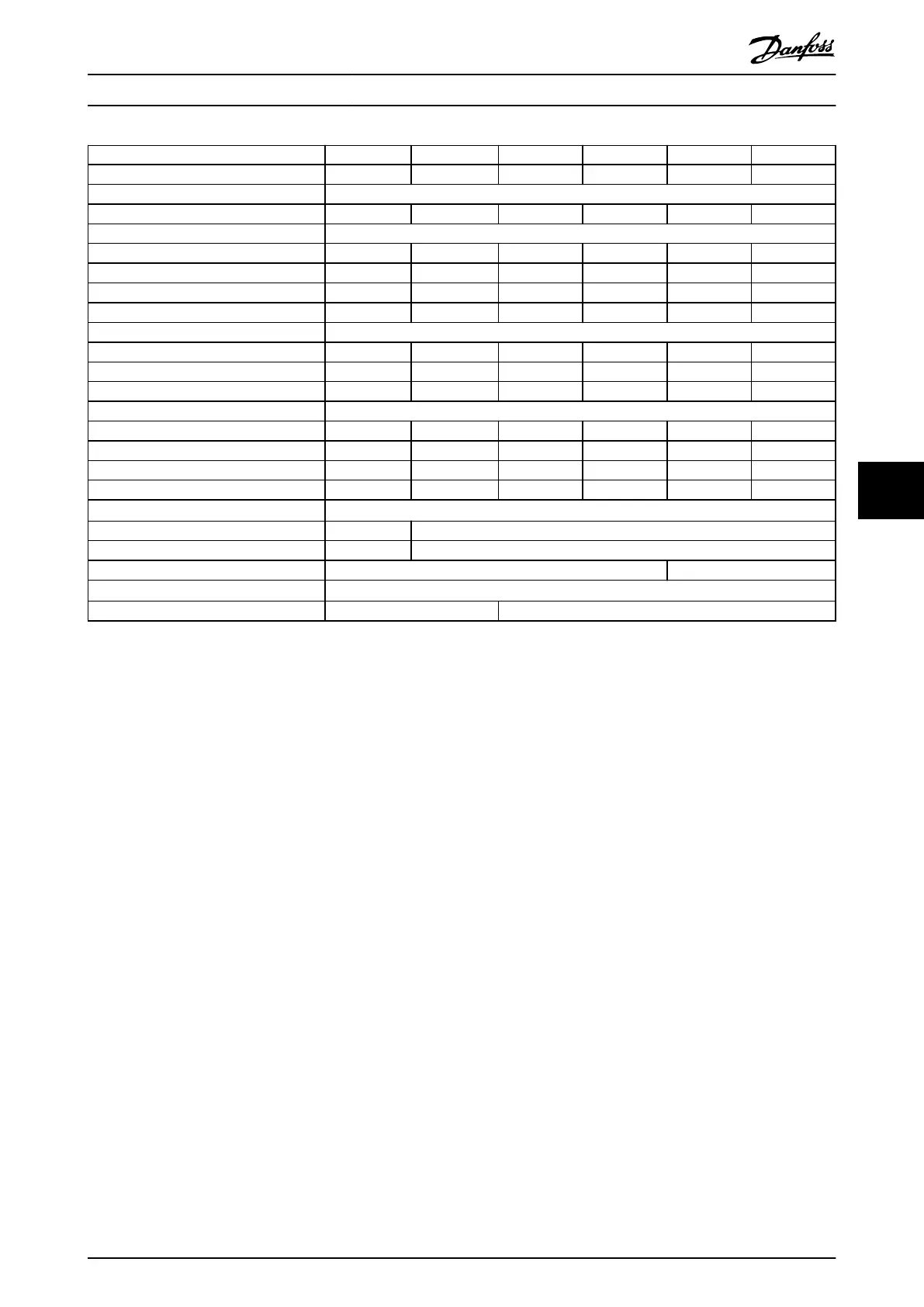
Power range N315 N400 N450 N500 N560 N630
Drive modules 2 2 2 2 2 2
Rectier conguration 12-pulse
High/normal load NO NO NO NO NO NO
Output current [A]
Continuous (at 550 V) 360 418 470 523 596 630
Intermittent (60 s overload) at 550 V 396 360 517 575 656 693
Continuous (at 575/690 V) 344 400 450 500 570 630
Intermittent (60 s overload) at 575/690 V 378 440 495 550 627 693
Input current [A]
Continuous (at 550 V) 355 408 453 504 574 607
Continuous (at 575 V) 339 490 434 482 549 607
Continuous (at 690 V) 352 400 434 482 549 607
Power losses [W]
Drive modules at 575 V 4401 4789 5457 6076 6995 7431
Drive modules at 690 V 4352 4709 5354 5951 6831 7638
AC bus bars at 575 V 540 541 544 546 550 553
DC bus bars during regeneration 88 88.5 90 91 186 191
Maximum cable size [mm
2
(mcm)]
Mains 2x120 (250) 4x120 (250)
Motor 2x120 (250) 4x120 (250)
Brake 4x70 (2/0) 4x95 (3/0)
Regeneration terminals
1)
4x120 (250)
Maximum external mains fuses 700 V, 550 A 700 V, 630 A
Table 7.3 FC 102, 525–690 V AC Mains Supply (2-Drive System)
1) If Danfoss bus bar kit is used.
Specications Installation Guide
MG37K302 Danfoss A/S © 08/2017 All rights reserved. 47
7 7
 Loading...


