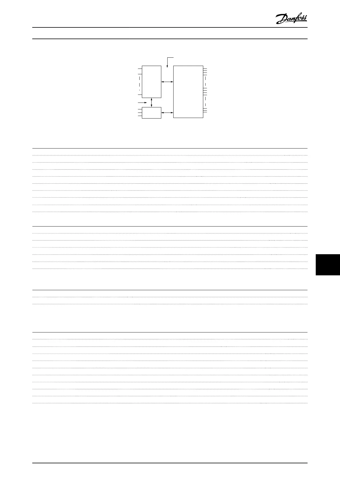
Mains
Functional
isolation
PELV isolation
Motor
DC-Bus
High
voltage
Control
+24V
RS485
18
37
130BA117.10
Illustration 11.6 PELV Isolation of Analog Inputs
Pulse inputs
Programmable pulse inputs 2
Terminal number pulse 29, 33
Max. frequency at terminal, 29, 33 110 kHz (Push-pull driven)
Max. frequency at terminal, 29, 33 5 kHz (open collector)
Min. frequency at terminal 29, 33 4 Hz
Voltage level see chapter 11.3.1 Digital inputs
Maximum voltage on input 28 V DC
Input resistance, R
i
approx. 4 kΩ
Pulse input accuracy (0.1–1 kHz) Max. error: 0.1% of full scale
Analog output
Number of programmable analog outputs 1
Terminal number 42
Current range at analog output 0/4-20 mA
Max. resistor load to common at analog output 500 Ω
Accuracy on analog output Max. error: 0.8% of full scale
Resolution on analog output 8 bit
The analog output is galvanically isolated from the supply voltage (PELV) and other high-voltage terminals.
Control card, RS-485 serial communication
Terminal number 68 (P,TX+, RX+), 69 (N,TX-, RX-)
Terminal number 61 Common for terminals 68 and 69
The RS-485 serial communication circuit is functionally seated from other central circuits and galvanically isolated from the
supply voltage (PELV).
Digital output
Programmable digital/pulse outputs 2
Terminal number 27, 29
1)
Voltage level at digital/frequency output 0-24 V
Max. output current (sink or source) 40 mA
Max. load at frequency output 1 kΩ
Max. capacitive load at frequency output 10 nF
Minimum output frequency at frequency output 0 Hz
Maximum output frequency at frequency output 32 kHz
Accuracy of frequency output Max. error: 0.1% of full scale
Resolution of frequency outputs 12 bit
1) Terminal 27 and 29 can also be programmed as input.
The digital output is galvanically isolated from the supply voltage (PELV) and other high-voltage terminals.
Specifications
Operating Instructions
MG37A202 Danfoss A/S © Rev. 2014-07-29 All rights reserved. 147
11 11

 Loading...


