Middle section (b)
Shows up to 5 variables with related unit, regardless of
status. In case of alarm/warning, the warning is shown
instead of the variables.
It is possible to toggle between 3 status read-out displays
by pressing [Status].
Operating variables with different formatting are shown in
each status screen.
Several values or measurements can be linked to each of
the displayed operating variables. The values/
measurements to be displayed can be defined via
parameters 0–20, 0–21, 0–22, 0–23, and 0–24.
Each value/measurement readout parameter selected in
parameters 0–20 to 0–24 has its own scale and number of
digits after a possible decimal point. Larger numeric values
are displayed with few digits after the decimal point.
Ex.: Current readout
5.25 A; 15.2 A 105 A.
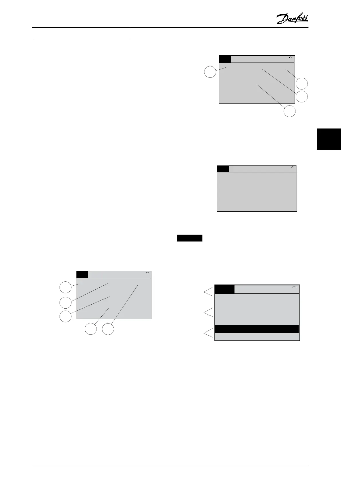
Status display I
This read-out state is standard after start-up or initiali-
sation.
Press [Info] to obtain information about the value/
measurement linked to the displayed operating variables
(1.1, 1.2, 1.3, 2, and 3).
See the operating variables shown in the display in
Illustration 5.2. 1.1, 1.2 and 1.3 are shown in small size. 2
and 3 are shown in medium size.
1.1
2
3
1.3
1.2
130BP041.10
799 RPM
Auto Remote Ramping
1 (1)
36.4 kw7.83 A
0.000
53.2 %
Status
Illustration 5.2 Status Display I - Operating Variables
Status display II
See the operating variables (1.1, 1.2, 1.3, and 2) shown in
the display in Illustration 5.3.
In the example, speed, motor current, motor power, and
frequency are selected as variables in the first and second
lines.
1.1, 1.2 and 1.3 are shown in small size. 2 is shown in large
size.
1.1
1.2
2
1.3
130BP062.10
207RPM
Auto Remote Running
1 (1)
24.4 kW5.25A
6.9
Hz
Status
Illustration 5.3 Status Display II - Operating Variables
Status display III
This state displays the event and action of the smart logic
control.
130BP063.10
778 RPM
Auto Remote Running
1 (1)
4.0 kW0.86 A
State: 0 o 0 (o)
When: -
Do: -
Status
Illustration 5.4 Status Display III - Operating Variables
NOTICE
Status display III is not available on the filter LCP.
Bottom section
always shows the state of the frequency converter in
Status mode.
Top section
Middle section
Bottom section
Status
43 RPM
1.4 Hz
Auto Remote Running
! Pwr.card temp (W29)
2.9%
5.44 A 25.3kW
1(1)
130BP074.10
!
Illustration 5.5 Bottom Section Status Mode
Display contrast adjustment
Press [status] and [
▲
] for darker display
Press [Status] and [
▼
] for brighter display
Indicator lights (LEDs):
If certain threshold values are exceeded, the alarm and/or
warning LED lights up. A status and alarm text appear on
the control panel.
The On LED is activated when the frequency converter
receives power from:
•
mains voltage
•
a DC bus terminal
User Interface
Operating Instructions
MG37A202 Danfoss A/S © Rev. 2014-07-29 All rights reserved. 43
5 5

 Loading...


