1-90 Motor Thermal Protection
Option: Function:
the motor is overloaded. Programme a
warning signal via one of the digital outputs.
The signal appears in the event of a warning
and if the frequency converter trips (thermal
warning).
[5] ETR warning
2
[6] ETR trip 2
[7] ETR warning
3
[8] ETR trip 3
[9] ETR warning
4
[10] ETR trip 4
NOTICE
If [20] ATEX ETR is selected, follow the instructions
described in the dedicated chapter of the VLT
®
AutomationDriveFC 301/FC 302 Design Guide and the
instructions given by the motor manufacturer.
NOTICE
If [20] ATEX ETR is selected, set 4-18 Current Limit to
150%.
PTC Thermistor Connection
1330
550
250
-20°C
175HA183.10
4000
3000
R
(Ω)
nominel
nominel -5°C
nominel +5°C
[°C]
Illustration 6.2 PTC profile
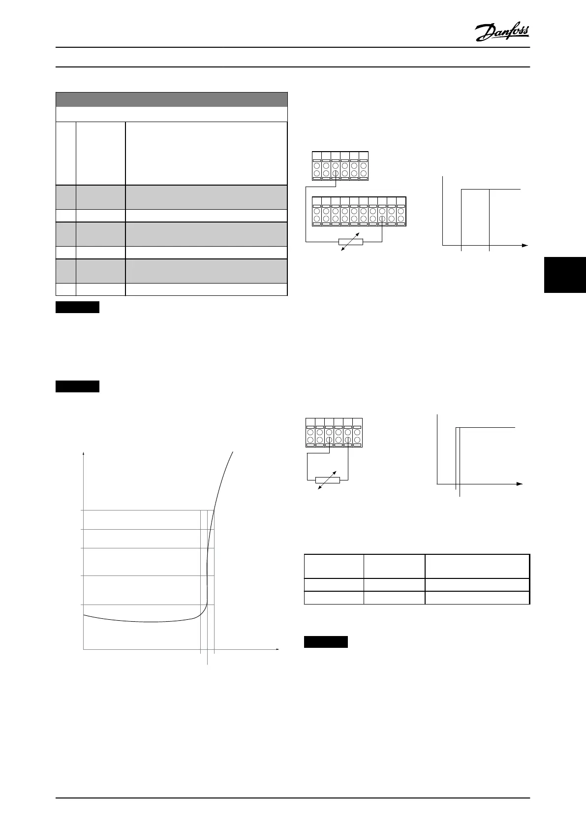
Using a digital input and 10 V as power supply:
Example: The frequency converter trips when the motor
temperature is too high.
Parameter set-up:
Set
parameter 1-90 Motor Thermal Protection to [2]
Thermistor Trip
Set parameter 1-93 Thermistor Source to [6] Digital Input
PTC / Thermistor
R
OFF
ON
<800 Ω
+10V
130BA152.10
>2.7 kΩ
12 13 18 37322719 29 33 20
5550
39 42 53 54
Illustration 6.3 Example with Digital Input and 10 V Power
Supply
Using an analog input and 10 V as power supply:
Example: The frequency converter trips when the motor
temperature is too high.
Parameter set-up:
Set parameter 1-90 Motor Thermal Protection to [2]
Thermistor Trip
Set parameter 1-93 Thermistor Source to [2] Analog Input 54
555039 42 53 54
R
<3.0 k Ω
>3.0 k Ω
+10V
130BA153.11
PTC / Thermistor
OFF
ON
Illustration 6.4 Example with Analog Input and 10 V Power
Supply
Input
Digital/analog
Supply Voltage
[V]
Threshold
Cut-out Values
Digital 10
< 800 Ω - > 2.7 kΩ
Analog 10
< 3.0 kΩ - > 3.0 kΩ
Table 6.2 Threshold Cut-out Values for Illustration 6.3 and Illustration 6.4
NOTICE
Check that the selected supply voltage follows the
specification of the thermistor element.
ETR
The calculations estimate the need for a lower load at
lower speed due to less cooling from the fan incorporated
in the motor.
Programming
Operating Instructions
MG37A202 Danfoss A/S © Rev. 2014-07-29 All rights reserved. 53
6 6

 Loading...


