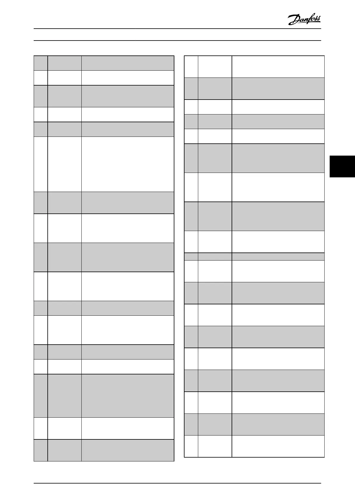
[16] Below speed,
low
Output speed is lower than the setting in
4-52 Warning Speed Low.
[17] Above speed,
high
Output speed is higher than the setting in
4-53 Warning Speed High.
[18] Out of
feedback
range
Feedback is outside the range set in
4-56 Warning Feedback Low and
4-57 Warning Feedback High.
[19] Below
feedback low
Feedback is below the limit set in
4-56 Warning Feedback Low.
[20] Above
feedback high
Feedback is above the limit set in
4-57 Warning Feedback High.
[21] Thermal
warning
The thermal warning turns on when the
temperature exceeds the limit in the
•
motor
•
frequency converter
•
brake resistor
•
thermistor
[22] Ready, no
thermal
warning
The frequency converter is ready for
operation and there is no overtemperature
warning.
[23] Remote,
ready, no
thermal
warning
The frequency converter is ready for
operation and is in [Auto on] mode. There
is no overtemperature warning.
[24] Ready, no
over-/ under
voltage
The frequency converter is ready for
operation and the mains voltage is within
the specified voltage range (see
chapter 11 Specifications).
[25] Reverse
Reversing. Logic ‘1’ when CW rotation of
the motor. Logic ‘0’ when CCW rotation of
the motor. If the motor is not rotating the
output follows the reference.
[26] Bus OK Active communication (no time-out) via
the serial communication port.
[27] Torque limit
and stop
Use in performing a coasting stop and in
torque limit condition. If the frequency
converter has received a stop signal and is
at the torque limit, the signal is logic ‘0’.
[28] Brake, no
brake warning
Brake is active and there are no warnings.
[29] Brake ready,
no fault
Brake is ready for operation and there are
no faults.
[30] Brake fault
(IGBT)
Output is logic ‘1’ when the brake IGBT is
short-circuited. Use this function to protect
the frequency converter if there is a fault
on the brake modules. Use the output/
relay to cut out the main voltage from the
frequency converter.
[31] Relay 123 Relay is activated when control word [0] is
selected in parameter group 8-**
Communications and Options.
[32] Mechanical
brake control
Enables control of an external mechanical
brake, see description in chapter 6.1.3 2-2*
Mechanical Brake.
[33] Safe stop
activated (FC
302 only)
Indicates that the safe stop on terminal 37
has been activated.
[40] Out of ref
range
Active when the actual speed is outside
settings in 4-52 Warning Speed Low to
4-55 Warning Reference High.
[41] Below
reference low
Active when actual speed is below speed
reference setting.
[42] Above
reference high
Active when actual speed is above speed
reference setting
[43] Extended PID
Limit
[45] Bus Ctrl Controls output via bus. The state of the
output is set in 5-90 Digital & Relay Bus
Control. The output state is retained in the
event of bus time-out.
[46] Bus Ctrl On at
timeout
Controls output via bus. The state of the
output is set in 5-90 Digital & Relay Bus
Control. If bus time-out the output state is
set high (On).
[47] Bus Ctrl Off at
timeout
Controls output via bus. The state of the
output is set in 5-90 Digital & Relay Bus
Control. If bus time-out the output state is
set low (Off).
[51] MCO
controlled
Active when an MCO 302 or MCO 305 is
connected. The output is controlled from
option.
[55] Pulse output
[60] Comparator 0
See parameter group 13-1* Comparators. If
comparator 0 is evaluated as TRUE, the
output goes high. Otherwise, it is low.
[61] Comparator 1
See parameter group 13-1* Comparators. If
comparator 1 is evaluated as TRUE, the
output goes high. Otherwise, it is low.
[62] Comparator 2
See parameter group 13-1* Comparators. If
comparator 2 is evaluated as TRUE, the
output goes high. Otherwise, it is low.
[63] Comparator 3
See parameter group 13-1* Comparators. If
comparator 3 is evaluated as TRUE, the
output goes high. Otherwise, it is low.
[64] Comparator 4
See parameter group 13-1* Comparators. If
comparator 4 is evaluated as TRUE, the
output goes high. Otherwise, it is low.
[65] Comparator 5
See parameter group 13-1* Comparators. If
comparator 5 is evaluated as TRUE, the
output goes high. Otherwise, it is low.
[70] Logic Rule 0
See parameter group 13-4* Logic Rules. If
logic rule 0 is evaluated as TRUE, the
output goes high. Otherwise, it is low.
[71] Logic Rule 1
See parameter group 13-4* Logic Rules. If
logic rule 1 is evaluated as TRUE, the
output goes high. Otherwise, it is low.
[72] Logic Rule 2
See parameter group 13-4* Logic Rules. If
logic rule 2 is evaluated as TRUE, the
output goes high. Otherwise, it is low.
Programming Operating Instructions
MG37A202 Danfoss A/S © Rev. 2014-07-29 All rights reserved. 65
6 6

 Loading...


