189
ASAHI KASEI [AK4358]
MS0203-J-01 2006/02
- 4 -
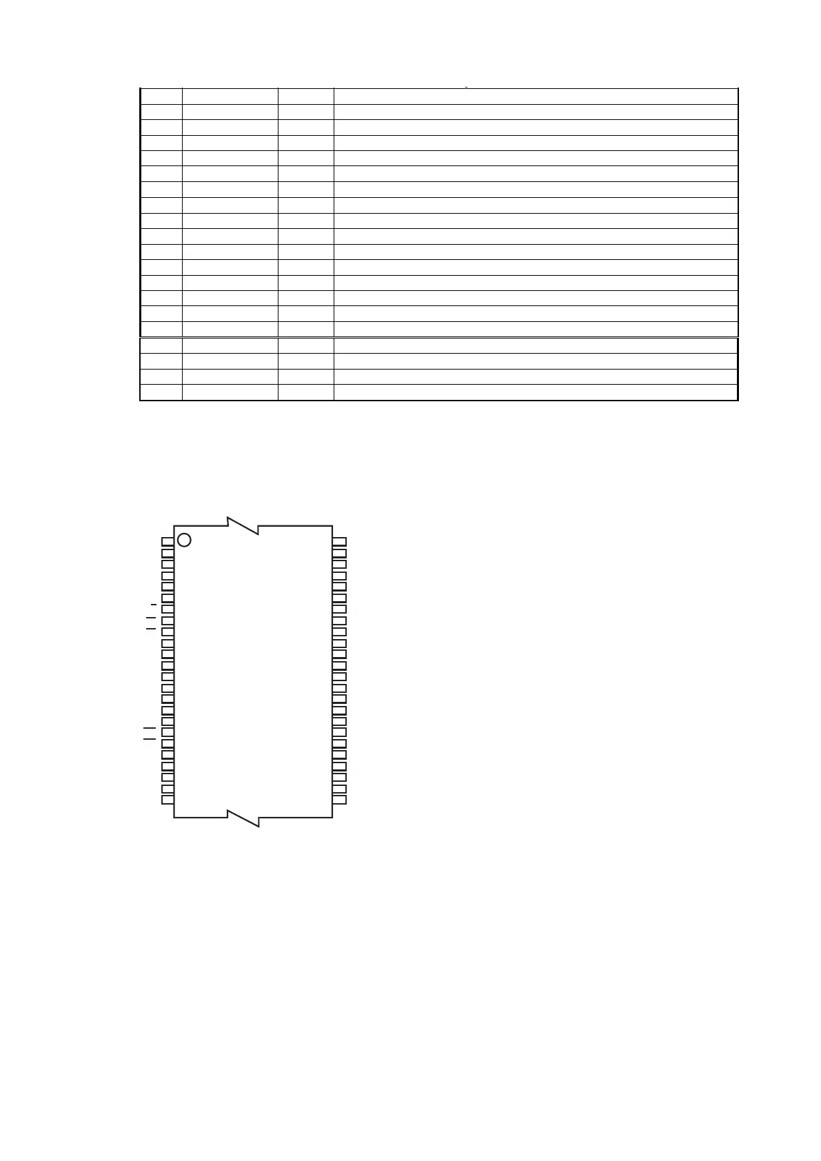
PIN/FUNCTION
No. Pin Name I/O Function
1 LOUT1- O DAC1 Lch Negative Analog Output Pin
2 LOUT1+ O DAC1 Lch Positive Analog Output Pin
3 DZF3 O Zero Input Detect 3 Pin
4 DZF2 O Zero Input Detect 2 Pin
5 DZF1 O Zero Input Detect 1 Pin
6 CAD0 I Chip Address 0 Pin
7 ACKSN I Auto Setting Mode Disable Pin (Pull-down Pin)
“L”: Auto Setting Mode, “H”: Manual Setting Mode
8 PDN I Power-Down Mode Pin
When at “L”, the AK4358 is in the power-down mode and is held in reset.
The AK4358 should always be reset upon power-up.
9 BICK I Audio Serial Data Clock Pin
10 MCLK I Master Clock Input Pin
An external TTL clock should be input on this pin.
11 DVDD -
Digital Power Supply Pin, +4.75∼+5.25V
12 DVSS - Digital Ground Pin
13 SDTI4 I DAC4 Audio Serial Data Input Pin
14 SDTI1 I DAC1 Audio Serial Data Input Pin
15 SDTI2 I DAC2 Audio Serial Data Input Pin
16 SDTI3 I DAC3 Audio Serial Data Input Pin
17 LRCK I L/R Clock Pin
18 I2C I Control Mode Select Pin
“L”: 3-wire Serial, “H”: I
2
C Bus
19 CCLK/SCL I Control Data Clock Pin
I2C = “L”: CCLK (3-wire Serial), I2C = “H”: SCL (I
2
C Bus)
20 CDTI/SDA I/O Control Data Input Pin
I2C = “L”: CDTI (3-wire Serial), I2C = “H”: SDA (I
2
C Bus)
21 CSN/CAD1 I Chip Select Pin
I2C = “L”: CSN (3-wire Serial), I2C = “H”: CAD1 (I
2
C Bus)
22 DCLK I DSD Clock Pin
23 DSDL4 I DAC4 DSD Lch Data Input Pin
24 DSDR4 I DAC4 DSD Rch Data Input Pin
25 DSDL1 I DAC1 DSD Lch Data Input Pin
26 DSDR1 I DAC1 DSD Rch Data Input Pin
27 DSDL2 I DAC2DSD Lch Data Input Pin
28 DSDR2 I DAC2 DSD Rch Data Input Pin
29 DSDL3 I DAC3 DSD Lch Data Input Pin
30 DSDR3 I DAC3 DSD Rch Data Input Pin
31 DIF0 I Audio Data Interface Format 0 Pin
32 ROUT4- O DAC4 Rch Negative Analog Output Pin
33 ROUT4+ O DAC4 Rch Positive Analog Output Pin
34 VREFH I Positive Voltage Reference Input Pin
35 AVDD -
Analog Power Supply Pin, +4.75∼+5.25V
36 AVSS - Analog Ground Pin
37 LOUT4- O DAC4 Lch Negative Analog Output Pin
38 LOUT4+ O DAC4 Lch Positive Analog Output Pin
39 ROUT3- O DAC3 Rch Negative Analog Output Pin
40 ROUT3+ O DAC3 Rch Positive Analog Output Pin
41 LOUT3- O DAC3 Lch Negative Analog Output Pin
42 LOUT3+ O DAC3 Lch Positive Analog Output Pin
43 ROUT2- O DAC2 Rch Negative Analog Output Pin
44 ROUT2+ O DAC2 Rch Positive Analog Output Pin
H27U1G8F2BTR-BC(HDMI:IC391)
ASAHI KASEI [AK4358]
MS0203-J-01 2006/02
- 5 -
45 LOUT2- O DAC2 Lch Negative Analog Output Pin
46 LOUT2+ O DAC2 Lch Positive Analog Output Pin
47 ROUT1- O DAC1 Rch Negative Analog Output Pin
48 ROUT1+ O DAC1 Rch Positive Analog Output Pin
Note: All input pins except pull-down pin should not be left floating.
絶対最大定格
(AVSS, DVSS=0V; Note 1)
Parameter Symbol Min Max Units
Power Supplies Analog
Digital
|AVSS-DVSS| (Note 2)
AVDD
DVDD
∆GND
-0.3
-0.3
-
6.0
6.0
0.3
V
V
V
Input Current (any pins except for supplies) IIN -
±10
mA
Digital Input Voltage VIND -0.3 DVDD+0.3 V
Ambient Operating Temperature Ta -40 85
°C
Storage Temperature Tstg -65 150
°C
Note 1. 電圧はすべてグランドピンに対する値です。
Note 2. AVSSとDVSSはアナロググランドに接続して下さい。
注意: この値を超えた条件で使用した場合、デバイスを破壊することがあります。
また通常の動作は保証されません。
推奨動作条件
(AVSS, DVSS=0V; Note 1)
Parameter Symbol Min Typ Max Units
Power Supplies
(Note 3)
Analog
Digital
AVDD
DVDD
4.75
4.75
5.0
5.0
5.25
5.25
V
V
Voltage Reference VREF AVDD-0.5 - AVDD V
Note 3. AVDDとDVDDの立ち上げシーケンスを考える必要はありません。
注意: 本データシートに記載されている条件以外のご使用に関しては、当社では責任負いかねますので十分
ご注意下さい。
Rev 1.1 / Sep. 2009 5
1
H27U1G8F2B Series
1 Gbit (128 M x 8 bit) NAND Flash
VCC
VSS
WP
CLE
ALE
RE
WE
CE IO0~IO7
R/B
NC
NC
NC
NCNC
NC NC
NC
CLE
ALE Vss
Vss
Vss
Vcc
Vcc
NC
NC
NC
WP
RE
CE
WE RB
NC
NC
NC
NC
NC
NC
NC
NC
NC
NC
NC
NC
NC
I/O0
I/O1
I/O9
I/O2
I/O3
I/O10
I/O11
I/O4
I/O15
I/O12 I/O14
I/O13
I/O6
I/O7 I/O5
NC
NC NC NC
NC
PRE
I/O8
NC
NCNC
NC NC
A
B
C
D
E
F
G
H
J
K
L
M
1 2 3 4 5 6 7 8 9 10
uhukGm
GGGGminh
GGGGGO_P
Figure 2 : 48-TSOP1 / 63-FBGA Contact, x8 Device
IO7 - IO0 Data Input / Outputs
CLE Command latch enable
ALE Address latch enable
CE Chip Enable
RE Read Enable
WE Write Enable
WP Write Protect
R/B
Ready / Busy
Vcc Power Supply
Vss Ground
NC No Connection
Figure 1 : Logic Diagram Table 1 : Signal Names
1&
1&
1&
1&
1&
1&
5%
5(
&(
1&
1&
9FF
9VV
1&
1&
&/(
$/(
:(
:3
1&
1&
1&
1&
1&
1&
1&
1&
1&
,2
,2
,2
,2
1&
1&
1&
9FF
9VV
1&
1&
1&
,2
,2
,2
,2
1&
1&
1&
1&
1$1')ODVK
7623
[
 Loading...