9
IP2368EN
EN
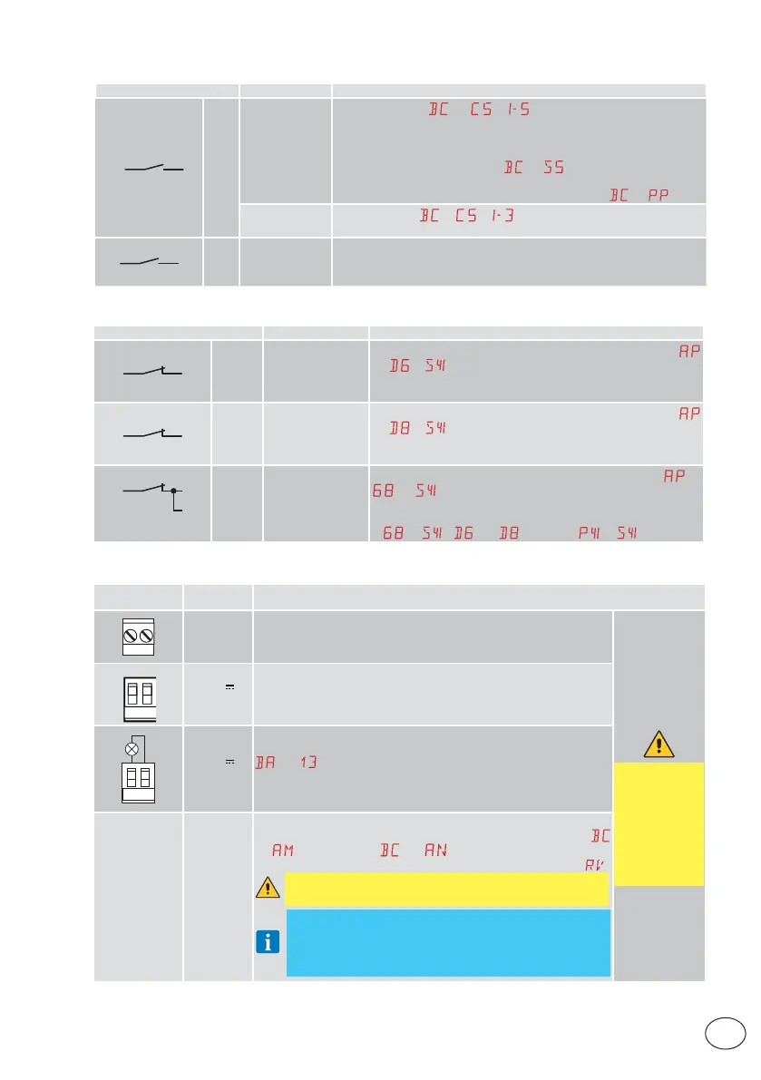
5.1 Command inputs
Command Function Description
30
5 NO
STEP-BY-
STEP
When selecting
→ → , closing the contact starts a
sequential opening or closing operation: opening-stop-clos-
ing-opening.
WARNING: if automatic closure is enabled, the duration of the stop
can be defined by selecting
→ .
The “opening-stop-closing-opening” sequence can be changed to
“opening-stop-closing-stop-opening” by selecting
→ .
OPENING
When selecting
→ → , the closure of the contact activates
an opening operation.
30
20 NO
PARTIAL
APERTURE
The closure of the contact activates a partial opening operation.
Once the automation stops, the partial opening control performs the
opposite operation to the one performed before the stop.
5.2 Safety inputs
Command Function Description
1
6
NC SAFETY STOP
For safety devices with self-test input: When selecting
→
→ , connect the output contact of the safety de-
vice to terminals 1-6 on the control panel (in series with the
photocell output contact, if installed).
1
8
NC
Closing safety
device
For safety devices with self-test input: When selecting
→
→ , connect the output contact of the safety de-
vice to terminals 1-8 on the control panel (in series with the
photocell output contact, if installed).
1
6
8
NC
CLOSING/OPEN-
ING SAFETY
DEVICE
For safety devices with self-test input: When selecting
→
→ , connect the output contact of the safety device
to terminals 1-6-8 on the control panel (in series with the
photocell output contact, if installed).
If
→ , and cannot be or .
6. Outputs and accessories
Output
Value of
accessories
Description
24V~
24V~
0.3A max
AC power supply to accessories
Output for power supply to external accessories.
The total sum
of the current
values deliv-
ered from the
24V~ outputs
1 and 30 must
never exceed
0.3A.
0
-
1
+
24V
0.3A max
Accessories power supply
Output for DC power supply to external accessories.
30
13
24V
3W max
Automation status lamp (configurable)
For the operating mode of output 30-13, refer to the selection
→ .
The current absorbed by the output 13, as well as the absorption
of the accessory inserted in the AUX1 is to be counted in total
deliverable from outputs 1 and 30 (300mA).
AUX 1
GOPAVRS
LAB9
BIXR2
BIXPR2
BIXLR42
LAN7S
The control panel has two slots for plug-in command and safety
boards. The action of the control board can be selected using
→
for AUX1 and → for AUX2. When using slot-in
radio boards, remove the RDX module. The display will show
.
WARNING: the plug-in cards must be inserted and removed
with the power supply disconnected.
NOTE: the current absorption of the accessories installed in the
slots AUX1/AUX2 if associated with output “1” by the relative jump-
er, must be considered in the total current deliverable by output
1 (0.3A). Differently if associated to “30” must be considered in
the calculation of the total current deliverable by output 30 (0.3A).
 Loading...


