INSTALLATION INSTRUCTIONS
2-20 L025317 Issue 5 July 2014
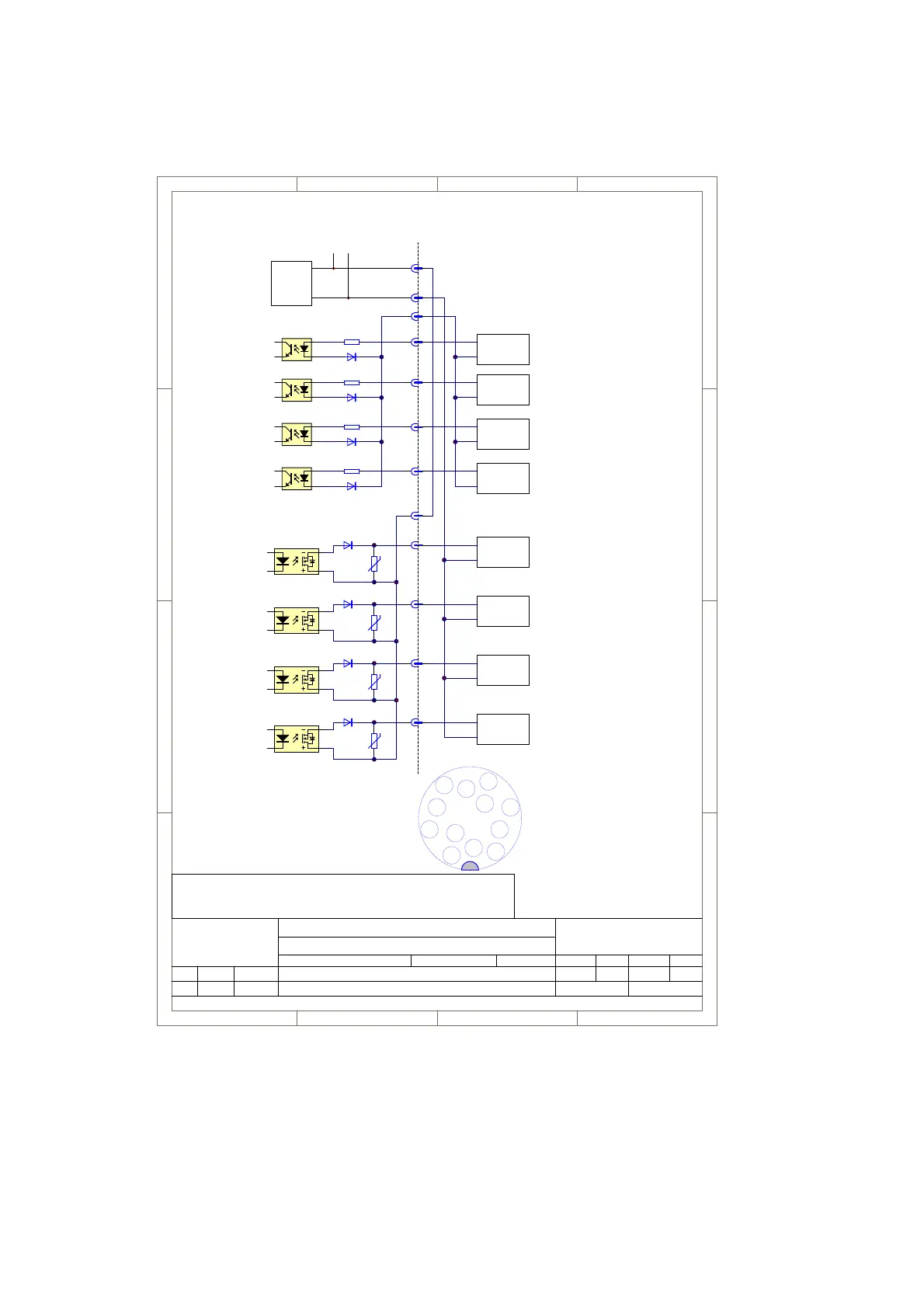
X4 Connector Schematic - Machine Control
1
1
2
2
3
3
4
4
D D
C C
B B
A A
Date Name Date Name
Ind. Chan.No. Changing Processed Reviewed
Title:
Project:
No.: 190010
X4 Machine Interface from DIB 1.53
D-Com Interface Documentation
D_Com_plugs_X4_MA-1_06-190010e.SchDoc
Date
14.05.14 HK
File:
Version: e06 Page of Size: A411
D-22547 Hamburg
Germany
Sator Laser GmbH
Fangdieckstraße 75a
© Sator Laser GmbH
Domino Group
Laser - Controller
A
D
B
J
K
Customer
L
M
PSU
24V
+
---
to the other Connectors
E
H
F
G
OPTOKO
C
LASER_START
4k4
R120
VDR: CT1210K25K/VDR25V
1
2 4
6
U24
AQV112KLA
1
2 4
6
U25
AQV112KLA
1
2 4
6
U26
AQV112KLA
R123
R126
floating
OPTOKO
OPTOKO
OPTOKO
Logic Input
MARK_CONTROL
Logic Input
PRINT_GO
Logic Input
PROG_IN
Logic Input
PRINTER_READY
Logic Output
PRINTER_BUSY
Logic Output
COMPILE_OK
Logic Output
+
-
+
-
Input
Output
PLC
PLC
+
-
Output
PLC
+
-
Output
PLC
+
-
Output
PLC
+
-
Input
PLC
+
-
Input
PLC
1.01 A: Plug pinout added 29.10.08 HK
1.02 B: "Project Run" renamed to "Laser Start". Input Resitances added 29.04.09 SW
c03: Add output X4M 21.09..12 HK
d04: corr. input resistors 22.10.12 HK d05 corr footer address; complete
history box 13.11.12 HK
e05: corr. diodes at dig. inputs 14.05.14 HK
D
A
B
C
E
H
L
J
F
G
K
M
X4 female plug solder side
(DC60V/0,5A)
1
2 4
6
U10
AQV112KLA
R39
X4M
Logic Output
+
-
Input
PLC
4k4
4k4
4k4
omino Laser GmbH
angdieckstraße 75a
-22547 Hamburg
Germany
© Domino Laser GmbH
 Loading...


