1
1
2
2
3
3
4
4
H H
G G
F F
E E
D D
C C
B B
A A
Date Name Date Name
Ind. Chan.No. Changing Processed Reviewed
Title:
Project:
No.: 124714
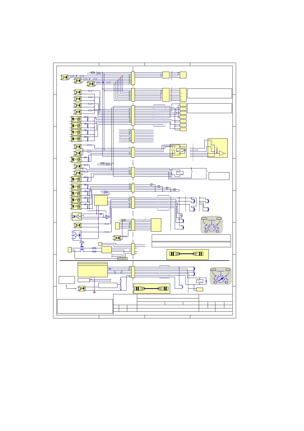
BCP7 Electrical Connections
Valid up to SCI 2.10
bcp7_electrical_connections-1_06-124714a.SchDoc
Date
24.06.14 PKU
File:
Version: a06 Page of Size: A311
D-22547 Hamburg
Germany
Domino Laser GmbH
Fangdieckstraße 75a
© Domino Laser GmbH
A 1.00 created 28.02.12 PKU
A 1.01 X4 Description 23.10.12 PKU
A 1.02 added : values of the input resistors 25.10.12 PKU
A 1.03 add : mains power connection 110V / 230V 15.01.13 PKU
A 1.04 without Cat2, new:Cat3=PL_d; Cat4=PL_e (Performance-Level...) 26.03.13 MAU
a05: Including Interlock X69 (shutter /fiber laser version) 13.02.14 HK/PKU
a06 change externe signal designation / remove interne s.d. 24.06.14 PKU
\\DEMK-DC1\group\Sator\R&D\Private\Elektronics\design\systems\bcp\bcp7\docu\bcp7_electrical_connections
1
2
3
4
5
6
7
X29
Laser Start
Print Go
Interlock X29
L1_SOURCE
PRINT_GO
IL1_INP
PRINTER READY OUTPUT
EXT_LSTART_IN
Printer Ready
3
1
4
5
6
2
7
WH
BN
GN
YE
GY
PK
BU
PL_d PL_e
5
1
3
4
1
3
5
A
B
C
D
E
F
G
H
J
K
L
M
X4
1
2
3
4
5
6
7
8
X6
1
2
3
4
5
6
7
8
X3
100R
PD input
Enc A input
Enc B input
In order to use the shaft encoder as a print-go source ensure that pins 3
and 4 are connected.
WARNING: In this configuration no additional
product detector should be connected.
LASER_START
4K4
MARK_CONTROL
4K4
PRINT GO
4K4
PROG IN
4K4
PRINTER_READY
PRINTER_BUSY
COMPILE_OK
Logic Input
Logic Input
Logic Input
Logic Input
Logic Output
Logic Output
Logic Output
DCinputs: 10-30V/Rin 2,2K
DC outputs max 24V /max 500mA
Machine Interface X4
+
-
PLC
Output
+
-
PLC
Output
+
-
PLC
Output
+
-
PLC
Output
+
-
PLC
Input
+
-
PLC
Input
+
-
PLC
Input
INP_COM
LASER_START
MARK_CTRL
PRINT_GO
PROG_IN
OUT_+COM
PRINTER_READY
PRINTER_BUSY
COMPILE_OK
NC
+ Supply
0V
A
B
Z
+ Supply
0V
A
B
Z
Z
A
B
PNP
Encoder
Input mode
Differential (Standard)
Encoder
Input mode
2
3
4
5
6
7
8
1
2
3
4
5
6
7
8
1
*
Shaft Encoder Input X6
*
*
*
Product Detect Interface X3
PNP
+ Supply
0V
Q
1
2
3
4
NPN
+ Supply
0V
Q
1
2
3
4
PD+ Product Detect positiv input
+24V floating, max 120mA
GNDF - floating Ground
CustomerBCP7 Controller
GND
+24V
GND
+24V
*
1
2
3
4
5
X2
Logic Output
Logic Output
Logic Output
Logic Output
GND
+24V
BLUE (+24V output)
Beacon Interface X2
Blue
Amber
Green
Red
1
2
3
4
5
6
X28
4K4Input Air OK
4K4Input Chiller OK
Output Air/Chiller ON
AIR_OK
CHILLER_OK
CHILLER_AIR_ON_+COM
Air/Chiller Control X28
1
2
3
4
5
6
X7
4K4Input Vacuum OK
4K4Input Filter OK
Output Exhauster ON
VAC_OK
FILTER_OK
VAC_ON_+COM
VAC_ON_NO
Exhauster with Relay
+
Exhauster with Logic Input
GND
2
1
3
4
5
6
Vacuum Control X7
GND
1
2
3
4
5
6
7
8
X23
RTS - Request to Send
CTS - Clear to Send
DTR - Data Terminal Ready
GND - Ground
DSR - Data Set Ready
RXD - Receive Data
TXD - Transmit Data
DCD - Data Carrier Detect
RS232 Interface X23
Pilz PNOZ S4
PL_ePL_d
mode
In2+ In2-
AA
WH
BN
GN
YE
GY
PK
BU
RD
BK
VT
GY-PK
RD-BU
X58 is only suitable for controller interconnection. X58 is needed to connect the power extension box for
D620i systems. Do not connect anything else to this connector!
X4M_OUT
Logic Output
Depends on Dynamark options!
Default Air/Chiller Control X28
Laser ON = Air ON
Laser ON = Chiller ON
Air OK respectively
water level OK!
Chiller OK!
The main cable controller to laser is available in two versions:
Main cable BCP7 Cheetah / Harting-plug
Main cable BCP7 Cheetah / Toughcon-plug
1K
100R1K
100R1K
Ethernet 2 (Remote Panel Interface) X59
1
2
3
4
5
6
7
X59
TX+_Transmit+
TX-_Transmit-
RX+_Receive+
RX-_Receive-
LSTART_INP
Remote Panel
Power Input
for future application
S11
S12
S21
S22
Pilz PNOZ S4
A2A1
Printer Ready Output
N.C.
N.C.
Laser start Input
PG/ Trigger Input
Opto Coupler
GND
+24V
4K4
2K2
ETH Control
GND
+24V
TX+
TX-
RX+
RX-
4K7
Logic Input
1
2
3
4
5
PE
N
PE
BN
BU
GN/YE
RD
BK
EXT_L_PWR+
EXT_L_PWR-
1
2
Molex MiniFit SR-2
AC Power line (110/230V)
Harting HAN 3A/5
BU
BN
N
L
BU
BN
2B
1A
2A
1B
1
2
3
DIB-X5
Sabre-3
L
N
PE
PE Housing
PE Chassis
F1
F2
EXT_L_PWR
L-out
N-out
PE
L-in
N-in
GN/YE
GN/YE
GN/YE
GN/YE
1
2
3
4
5
6
7
X69
Laser Start
IL1_SOURCE +24V
IL1_INP
EXTERNAL LASER START INPUT
3
1
4
5
6
2
7
WH
BN
GN
YE
GY
PK
BU
PL_e
Pilz PNOZ S4
PL_ePL_d
mode
In2+ In2-
AA
Pilz mm0p
Programmed with shutter feedback verification
Safety 1 source
Safety 1 feedback
PSU 24V
+
-
4
3
1
2
U5
PC357N2TJ00F
Filter / input ref.1.6V /
start logic / driver
R71
20k
R72
3k3
Case GND
Via X68 to:
BCP7 / X29
(floating system)
To laser and board supply
X29X68
BCP7 ControllerFb-Laser Extension Box
DLG: 122383
Connect this cable for the shutter function
Door lock output
X24
X24
BCP7 ControllerFb-Laser Extension Box
DLG: 122384
Install this cable for the fiber laser internal data connection.
L2_GND
IL2_INP
DOOR LOCK OUTPUT
IL2 (a)
IL2 (b)
IL2 (a)
IL2 (b)
GND / PE
+
-
PLC
Output
7
2
6
Laser Start
Door lock (optional)
Interlock X69 (shutter /fiber laser version)
2.10 3.00
2.10 3.00
PD- Product Detect negativ input
PD+ Product Detect positiv input
+24V floating, max 120mA
GNDF - floating Ground
PD- Product Detect negativ input
CHA+ Encoder Channel A positiv input
CHB+ Encoder Channel B positiv input
CHA- Encoder Channel A negativ input
CHB- Encoder Channel B negativ input
+24V floating
GNDF - floating Ground
GNDF - floating Ground
+24V floating
GNDF - floating Ground
CHILLER_AIR_ON_NO
+24V floating
GNDF - floating Ground
AMBER (+24V output)
GREEN (+24V output)
RED(+24V output)
+24V floating
GNDF - floating Ground
L
 Loading...


