Eaton 9155 UPS (8–15 kVA) User’s Guide 164201553—Rev H0 37
Figure 21. Attaching the L-Brackets
L-Bracket and Screws
UPS Wiring
Access Cover
5. Remove the MBM/PDM wiring access cover and one of the conduit landing plates and retain (See
Figure 22).
6. Tilt the top of the module forward and slide the module onto the L-brackets. The top left flange on the
module fits up under the UPS electronics unit through an access slot.
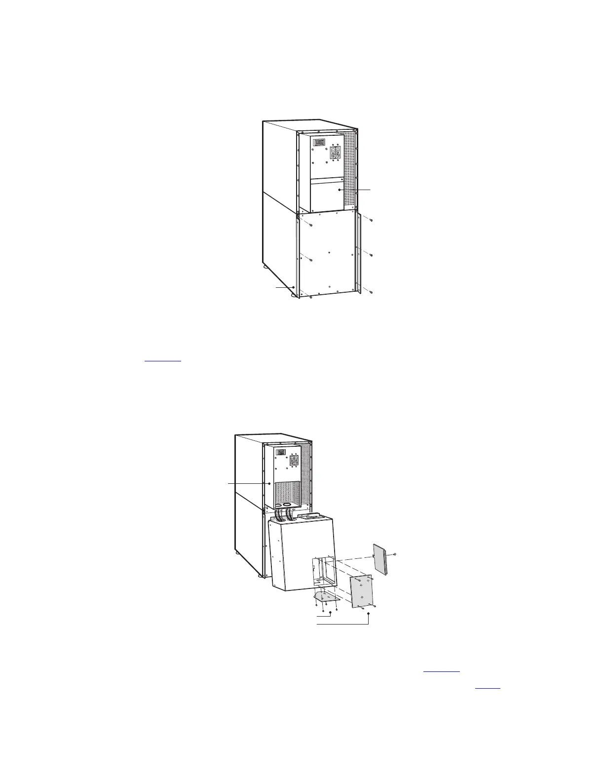
Figure 22. Installing the MBM or PDM
MBM/PDM Wiring
Access Cover
UPS Electronics
Unit
Conduit Landing Plates
NOTE: MBM Shown
7. Secure the sides of the module to the L-brackets using six screws (see Figure 23).
8. Secure the top of the module to the top cabinet using four of the screws removed in Step 1.
UPS System Installation
 Loading...


