Eaton 9155 UPS (8–15 kVA) User’s Guide 164201553—Rev H0 49
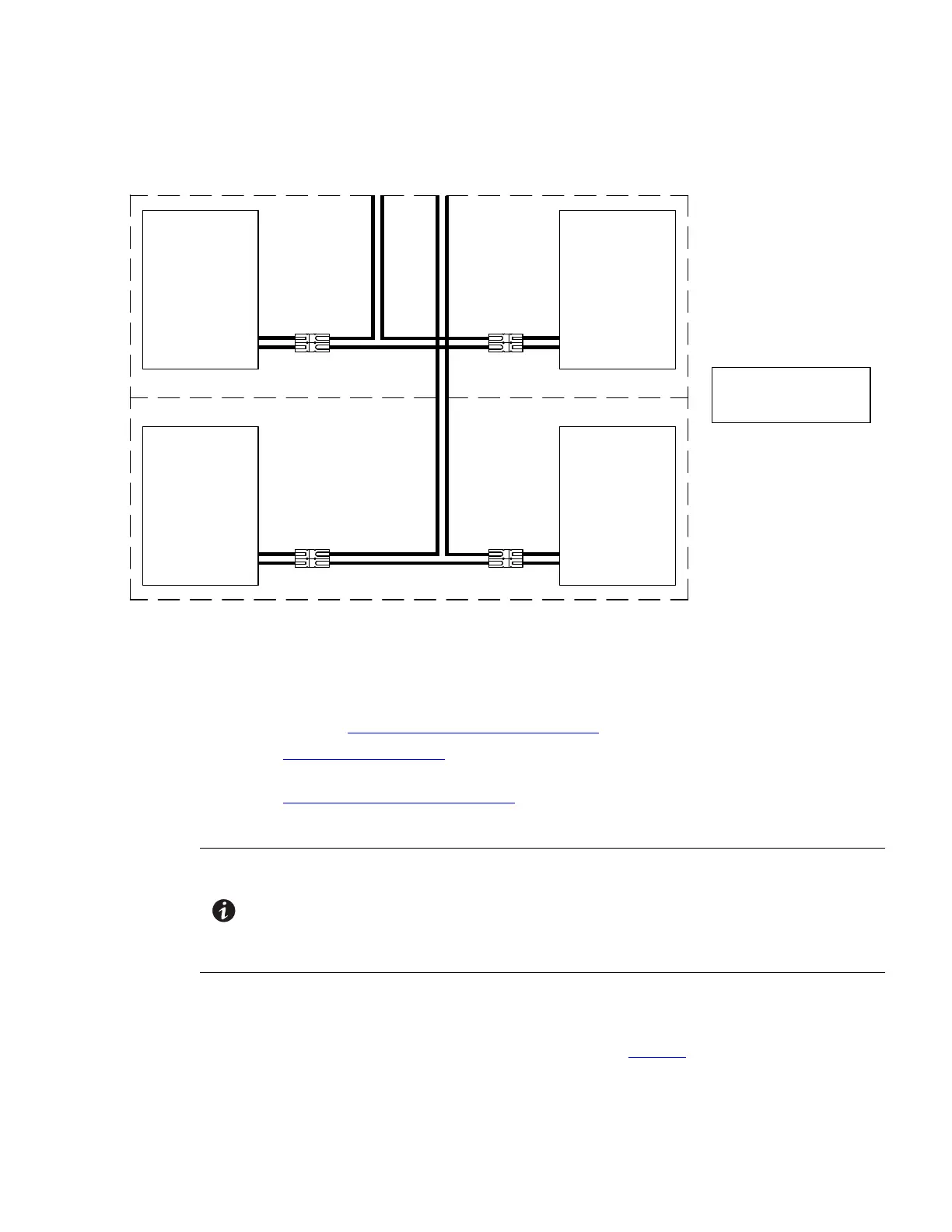
Figure 35. Internal Battery Tray Wiring Diagram
Battery Tray
Assembly
Battery Tray
Assembly
Battery Tray
Assembly
Battery Tray
Assembly
DIAGRAM REPRESENTS
EACH TWO-SHELF
CABINET MODULE
RED
BLACK
WHITE
BLACK
RED
RED
BLACK
WHITE
BLACK
RED
RED
BLACK
RED
BLACK
5. Repeat these steps to connect each battery tray to the UPS-Battery wiring harness.
6. Continue to one of the following sections:
• See paragraph 4.6 Extended Battery Module Installation to install optional EBMs.
• See Chapter 6 Communication to install UPS communication options, such as X-Slot cards or remote
emergency power-off (REPO).
• See Chapter 7 UPS Operating Instructions to start up the UPS.
44..66 EExxtteennddeedd BBaatttteerryy MMoodduullee IInnssttaallllaattiioonn
NOTE 1 A maximum of 22 battery strings can be installed in one configuration, including UPS
batteries (4 EBM-64 models or 3 EBM-96 models). UPS-32 models contain 2 strings;
UPS-64 models contain 4 strings; EBM-64 models contain 4 strings; and EBM-96
models contain 6 strings.
NOTE 2 For non-seismic installations, you MUST install the stabilizing bracket on all 3-high
cabinets. The stabilizing bracket is optional for 2-high cabinets.
To install the optional Extended Battery Module (EBM):
1. Position the EBM adjacent to the next cabinet.
2. Verify that all battery circuit breakers are in the OFF position (see Figure 36).
3. Remove the two ground straps from the EBM rear panel.
UPS System Installation
 Loading...