Eaton 9155 UPS (8–15 kVA) User’s Guide 164201553—Rev H0 59
CChhaapptteerr 66 CCoommmmuunniiccaattiioonn
This section describes the:
• DB-9 communication port
• X-Slot cards
• Power Management Software
• Remote emergency power-off (REPO)
• Relay output contacts
• Programmable signal inputs
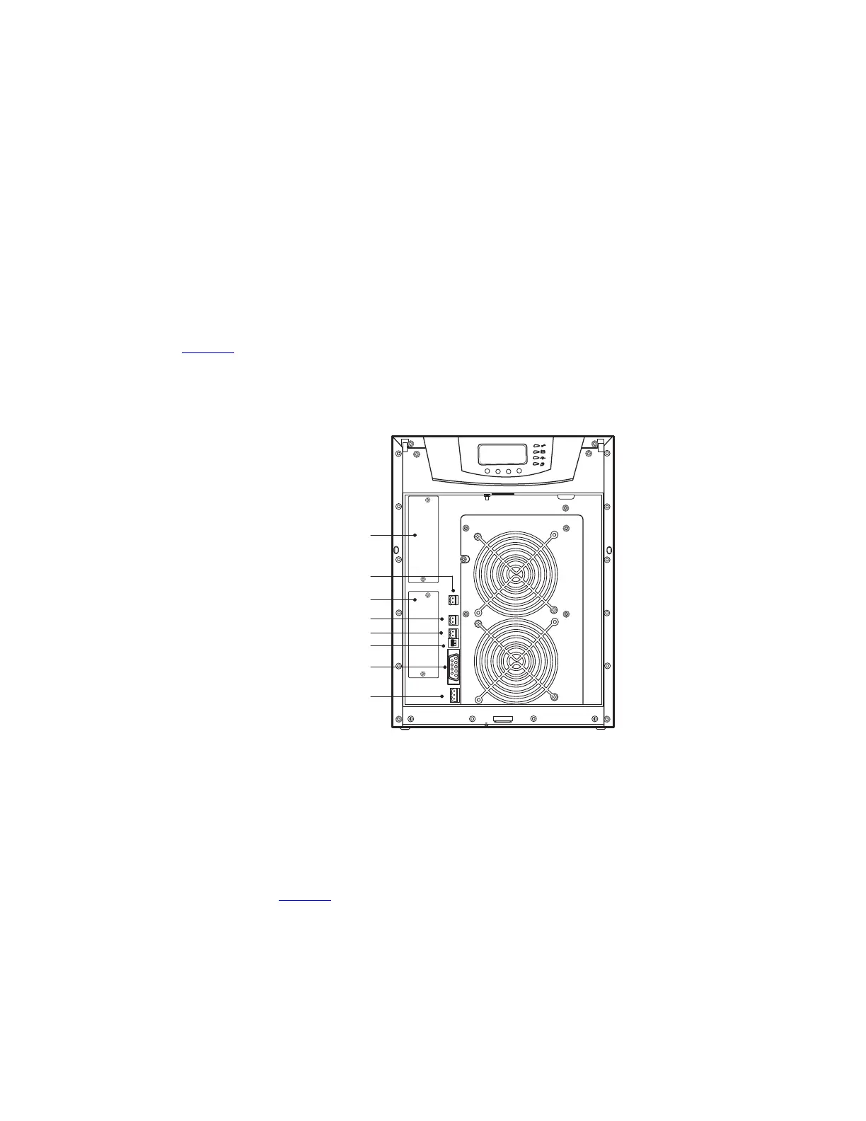
Figure 43 shows the location of the communication options and control terminals on the UPS.
Figure 43. Communication Options and Control Terminals
2
1
3
2
1
2
1
2
1
2
1
DB-9 Communication Port
REPO (normally closed)
REPO (normally open)
Signal Input 2
Signal Input 1
X-Slot Communication Bay #2
X-Slot Communication Bay #1
Relay Output Contacts
66..11 IInnssttaalllliinngg CCoommmmuunniiccaattiioonn OOppttiioonnss aanndd CCoonnttrrooll TTeerrmmiinnaallss
To access and install the communication options and control terminals:
1. Remove the front covers of all cabinets, starting with the top cabinet.
Press and release the handle latch at the bottom of each cover and then lift the cover up and off the
cabinet (see Figure 44).
 Loading...